Combination of Pseudobrookite Oxide and Low Loading of PGM as High Sulfur-Resistant Catalyst for Diesel Oxidation Applications

a technology of pseudobrookite oxide and pgm, which is applied in the direction of metal/metal-oxide/metal-hydroxide catalysts, physical/chemical process catalysts, and separation processes, etc., can solve the problems of significant catalyst deactivation, increase the cost of catalyst systems, and high cost of pgms, so as to avoid sulfur poisoning, increase the efficiency, and avoid oxidation

Inactive Publication Date: 2016-12-01
CLEAN DIESEL TECHNOLOGIES
View PDF4 Cites 15 Cited by
  • Summary
  • Abstract
  • Description
  • Claims
  • Application Information

AI Technical Summary

Benefits of technology

[0010]It is an object of the present disclosure to describe embodiments of SPGM catalyst systems having a high catalytic activity and resistance to sulfur poisoning. In these embodiments, a catalytic layer of 5 g / ft3 of PGM active components is synergized with Zero-PGM (ZPGM) catalyst compositions including a pseudobrookite structure in a separate catalytic layer. In some embodiments, the disclosed 2-layer SPGM catalysts can provide catalyst systems exhibiting high oxidation activity as well as sulfur resistance.
[0014]Still further to these embodiments, the combined catalytic properties of the layers in SPGM catalyst systems can provide more efficiency in NO oxidation and more stability against sulfur poisoning.

Problems solved by technology

In diesel engines, the sulfur present in the exhaust gas emissions may cause significant catalyst deactivation, even at very low concentrations due to the formation of strong metal-sulfur bonds.
Unfortunately, utilizing high loadings of PGM within catalyst systems increases the cost of the catalyst systems because PGMs are expensive.
PGMs are expensive because they are scarce, have a small market circulation volume, and exhibit constant fluctuations in price and constant risk to stable supply, amongst other issues.

Method used


Image

  • Combination of Pseudobrookite Oxide and Low Loading of PGM as High Sulfur-Resistant Catalyst for Diesel Oxidation Applications
  • Combination of Pseudobrookite Oxide and Low Loading of PGM as High Sulfur-Resistant Catalyst for Diesel Oxidation Applications
  • Combination of Pseudobrookite Oxide and Low Loading of PGM as High Sulfur-Resistant Catalyst for Diesel Oxidation Applications

Examples


Embodiment Construction

[0022]The present disclosure is here described in detail with reference to embodiments illustrated in the drawings, which form a part here. Other embodiments may be used and / or other changes may be made without departing from the spirit or scope of the present disclosure. The illustrative embodiments described in the detailed description are not meant to be limiting of the subject matter presented here.

DEFINITIONS

[0023]As used here, the following terms have the following definitions:

[0024]“Catalyst” refers to one or more materials that may be of use in the conversion of one or more other materials.

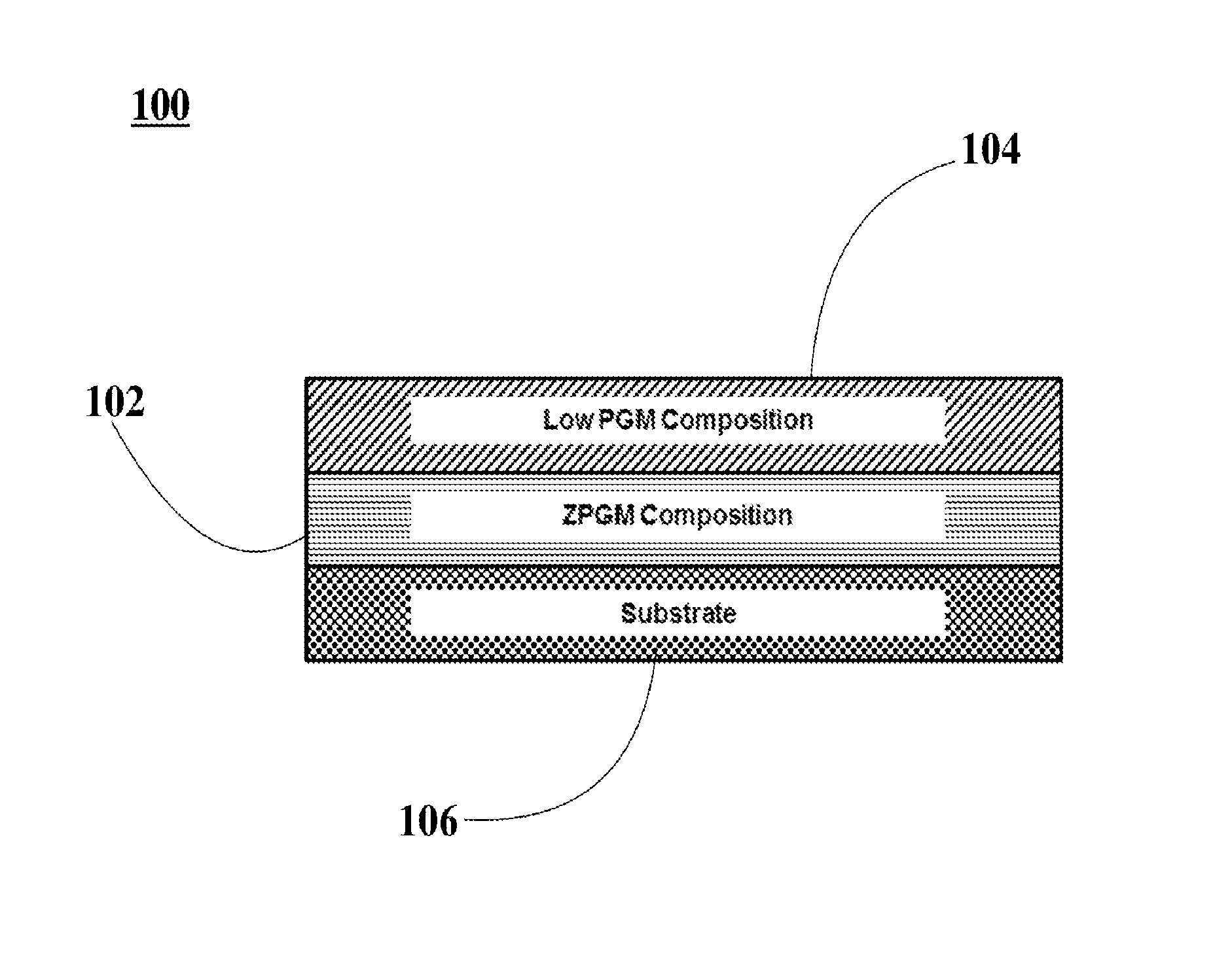
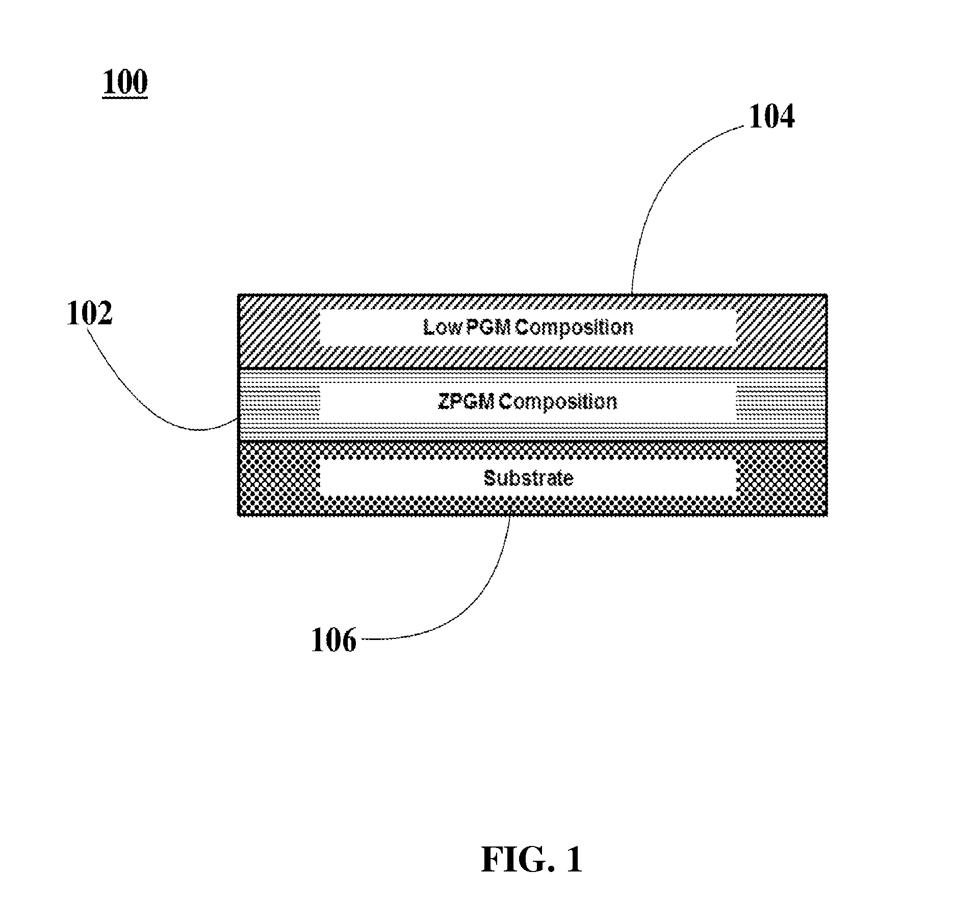
[0025]“Washcoat” refers to at least one coating including at least one oxide solid that may be deposited on a substrate.

[0026]“Substrate” refers to any material of any shape or configuration that yields a sufficient surface area for depositing a washcoat and / or overcoat.

[0027]“Overcoat” refers to at least one coating that may be deposited on at least one washcoat or impregnation layer.

[002...


PUM

PropertyMeasurementUnit
isothermal temperatureaaaaaaaaaa
temperatureaaaaaaaaaa

Abstract

Sulfur-resistant synergized platinum group metals (SPGM) catalysts with significant oxidation capabilities are disclosed. Catalytic layers of SPGM catalyst samples are prepared using conventional synthesis techniques to build a washcoat layer completely or substantially free of PGM material. The SPGM catalyst includes a washcoat layer comprising YMn2O5 (pseudobrookite) and an overcoat layer including a Pt / Pd composition with total PGM loading of at or below 5.0 g / ft3. Resistance to sulfur poisoning and catalytic stability is observed under 5.2 gS / L condition to assess significant improvements in NO oxidation, and HC and CO conversions.

Description

BACKGROUND[0001]Field of the Disclosure[0002]This disclosure relates generally to diesel oxidation catalysts for the treatment of exhaust gas emissions from diesel engines, and more particularly, to sulfur-resistant synergized platinum group metals (SPGM) catalyst systems with low platinum group metals (PGM) loading, according to a catalyst structure including at least two distinct layers.[0003]Background Information[0004]Diesel oxidation catalysts (DOCs) include PGM deposited on a metal support oxide. DOCs are used in treating diesel engine exhaust to reduce nitrogen oxides (NOx), hydrocarbons (HC), and carbon monoxide (CO) gaseous pollutants. The DOCs reduce the gaseous pollutants by oxidizing them.[0005]Conventional catalytic converter manufacturers utilize a single PGM catalyst within their diesel exhaust systems. Since a mixture of platinum (Pt) and palladium (Pd) catalysts within the PGM portion of a catalytic system offer improved stability, the catalytic converter manufactur...

Claims


Application Information

Patent Timeline
Patent Type & Authority Applications(United States)
IPC IPC(8): B01J23/656B01J35/00B01J21/06B01J23/40
CPCB01J23/6562B01J21/066B01J35/0006B01J23/40B01J2523/00B01J2523/36B01J2523/72B01J2523/48B01J2523/31B01J2523/828B01J2523/824B01D53/944B01D53/9468B01D2255/1021B01D2255/1023B01D2255/1025B01D2255/1026B01D2255/1028B01D2255/104B01D2255/2061B01D2255/2063B01D2255/2065B01D2255/2066B01D2255/2068B01D2255/20715B01D2255/2073B01D2255/20738B01D2255/20761B01D2255/2092B01D2255/40B01D2255/65B01D2255/9022B01J23/002B01J23/34B01J37/0036B01J37/0201B01J37/0244B01J37/0248B01J37/088
Inventor NAZARPOOR, ZAHRAGOLDEN, STEPHEN J.
Owner CLEAN DIESEL TECHNOLOGIES
Why Eureka
Try Eureka