Methods to identify macromolecule binding and aggregation prone regions in proteins and uses therefor

a macromolecule and protein technology, applied in the field of methods to identify macromolecule binding and aggregation prone regions in proteins, can solve the problems of antibody thermodynamic instability, reduced product efficiency, and possible side effects such as immunological response upon administration, so as to improve stability and reduce the propensity for aggregation

Active Publication Date: 2016-12-15
NOVARTIS AG +1
View PDF1 Cites 0 Cited by
  • Summary
  • Abstract
  • Description
  • Claims
  • Application Information

AI Technical Summary

Benefits of technology

[0016]The present invention provides methods and computational tools based, at least in part, on computer simulations that identify aggregation prone regions of a protein. Substitutions may then be made in these aggregation prone regions to engineer proteins with enhanced stability and / or a reduced propensity for aggregation.

Problems solved by technology

The recent tremendous increase of protein-based pharmaceuticals has created a new challenge.
As aggregates form, not only the efficacy of the product decreases, but side effects such as immunological response upon administration may occur.
However, these antibodies are thermodynamically unstable under these conditions and degrade due to aggregation.
The aggregation in turn leads to a decrease in antibody activity making the drug ineffective and can even generate an immunological response.
However, the main limitation of the seven-parameter model is that all residues in the sequence were given same relative importance.
Although, it is not possible to calculate absolute rates of aggregation with TANGO, it provides a qualitative comparison between peptides or proteins differing significantly in sequence.
More detailed models, such as the intermediate resolution model followed but suffered from the same inability to accurately represent protein secondary and tertiary structures.
The explicit model is more accurate but also more computationally demanding.
However, because such a procedure is very computationally demanding, especially for large proteins such as antibodies there does not appear to be full antibody atomistic simulation in the literature.
Although these additives enable proteins to be stabilized to some degree in solution, they suffer from certain disadvantages such as the necessity of additional processing steps for additive removal.

Method used


Image

  • Methods to identify macromolecule binding and aggregation prone regions in proteins and uses therefor
  • Methods to identify macromolecule binding and aggregation prone regions in proteins and uses therefor
  • Methods to identify macromolecule binding and aggregation prone regions in proteins and uses therefor

Examples


example 1

Molecular Dynamics Simulation Methodology

[0143]Molecular dynamics simulations were performed for a full antibody using an all atom model. The initial structure for simulation for the full antibody was obtained from the X-ray structures of individual Fab and Fc fragments. The X-ray structure of a proof-of-concept (POC) Fab fragment was selected for modeling onto the X-ray structure of Fc obtained from the IgG1 antibody 1HZH (Saphire et al., Science. 2001, 293, 1155). 1HZH was chosen since the X-ray structure is known for the full antibody and since the Fc structure is the same for all of the IgG1 class of antibodies. The structure of a full POC antibody was then obtained by aligning the Fab and Fc fragments using the 1HZH structure as a model template. In order to align the fragments at the correct distance and orientation, the RMSD (Root Mean Square Deviation) was minimized between the common CYS residues of the fragments and the full antibody template (1HZH). The CYS residues were ...

example 2

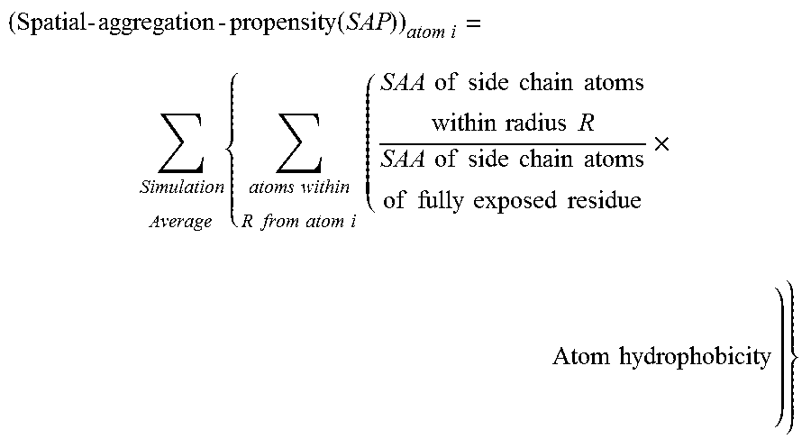
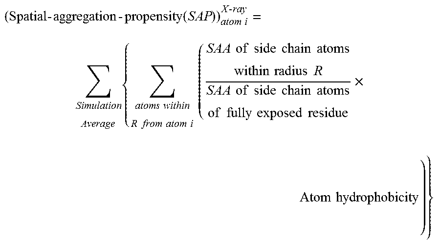
Calculation of the Spatial Aggregation Propensity (SAP)

[0146]In order to overcome the shortcomings of SAA, a new parameter was defined called ‘Spatial-Aggregation-Propensity’ as described above.

[0147]In this example the ‘Spatial-Aggregation-Propensity’ was calculated for spherical regions with radius R centered on every atom in the antibody described in Example 1. The value of Spatial-Aggregation-Propensity was thus evaluated with a 30 ns simulation average for the Fc-fragment of the antibody for two different radii of patches (R=5 Å, 10 Å) (One of skill in the art will appreciate various time steps for simulation may be chosen according to the computational resources available and the desired resolution of the result). In both cases it was noticed that the majority of values were negative, indicating that most exposed regions are hydrophilic. This was as expected since most of the exposed protein surface is usually hydrophilic. It was also observed that there are a few regions with...

example 3

Selection of Antibody Sites for Stability Engineering

[0153]The sites to be engineered for enhanced antibody stability were selected on the basis of the SAP parameter. This spatial parameter accounts for (1) Solvent accessible area (SAA) of each residue, (2) the residue's hydrophobicity, and (3) the spatial contributions of all residues within a certain radius. In this example, the hydrophobic residues that correspond to the positive peaks in CH2 were changed to non-hydrophobic residues. It was expected that this would improve the overall protein stability. The two selected sites (A1 and A2) correspond to two very hydrophobic residues. An analysis was undertaken of substitutions of these residues with lysine, a very hydrophilic amino acid with a positively charged side chain. Variant A1 and Variant A2 differ from wild-type by single amino substitution.


PUM

PropertyMeasurementUnit
temperatureaaaaaaaaaa
pHaaaaaaaaaa
concentrationaaaaaaaaaa

Abstract

The present invention provides methods and computational tools based, at least in part, on computer simulations that identify macromolecule binding regions and aggregation prone regions of a protein. Substitutions may then be made in these aggregation prone regions to engineer proteins with enhanced stability and / or a reduced propensity for aggregation. Similarly, substitutions may then be made in these macromolecule binding regions to engineer proteins with altered binding affinity for the macromolecule.

Description

CROSS-REFERENCE TO RELATED APPLICATIONS[0001]This application is a Divisional of U.S. patent application Ser. No. 13 / 000,353, claiming an international filing date of Jun. 19, 2009, which is a U.S. National Phase of International Patent Application No. PCT / US2009 / 047954, filed Jun. 19, 2009, which claims the benefit of U.S. Provisional Patent Application No. 61 / 074,466, filed Jun. 20, 2008, all of which are hereby incorporated by reference in the present disclosure in their entirety.SUBMISSION OF SEQUENCE LISTING ON ASCII TEXT FILE[0002]The content of the following submission on ASCII text file is incorporated herein by reference in its entirety: a computer readable form (CRF) of the Sequence Listing (file name: 619672000310 SeqList.txt, date recorded: Jun. 27, 2016, size: 2 KB).BACKGROUND OF THE INVENTION[0003]Understanding and controlling protein stability has been a coveted endeavor to Biologists, Chemists, and Engineers. The first link between amino acid substitution and disease...

Claims


Application Information

Patent Timeline
Patent Type & Authority Applications(United States)
IPC IPC(8): G06F19/16C07K14/71C07K16/00G06F19/24G16C20/50
CPCG06F19/16C07K16/00C07K2317/94A61K38/00C07K14/71G16B15/00G16B40/00G16C99/00A61P37/00G16B15/20G16C20/50G16C10/00G16B99/00G16B5/00G16B20/00A61K39/39591C07K16/1063C07K16/18
Inventor CHENNAMSETTY, NARESHHELK, BERNHARDTROUT, BERNHARDTKAYSER, VEYSELVOYNOV, VLADIMIR
Owner NOVARTIS AG
Why Eureka
Try Eureka