In-situ purification island structure and the construction method thereof

a technology of purification island and purification water, which is applied in the direction of sustainable biological treatment, biological water/sewage treatment, water cleaning, etc., can solve the problems of water sub-quantity increase, damage to the bed soil of rivers and lakes, and pollution of water bodies, so as to improve the purification effect of polluted water, save costs, and improve the effect of water quantity

Active Publication Date: 2016-12-29
NANJING UNIV ECOLOGICAL RES INST OF CHANGSHU
View PDF0 Cites 9 Cited by
  • Summary
  • Abstract
  • Description
  • Claims
  • Application Information

AI Technical Summary

Benefits of technology

[0008]The primary task of the present invention is to provide an in-situ purification island structure, which will help to intercept the pollutants in the river systems to improve the purifying effect of polluted water obviously, and will help to reflect the long-lasting effect of maintenance-fr

Problems solved by technology

Although the protection of water environment has become the consensus of the people, a lot of industrial and urban sewage is discharged directly to rivers and lakes without required treatment due to the limitation of variety of subjective and objective conditions, which pollutes the water bodies and also damages the bed soil of rivers and lakes.
Especially when the water is contaminated by such as nitrogen, phosphorus, organic pollutants and various heavy metals elements, the situation of water sub-quantity becomes more seriously.
However, because of large flow of river and complex morphology and the natural purification of water is a complex process affected by many factors, it will not only cost high in construction, operation and maintenance but also has poor landscape according to the conventional treatment of sewage.
Although technical effect in the paragraph 0010 of description can be achieved, the solution in the patent still has disadvantages: firstly, it's construction tedious due to the need of laying pipelines (distribu

Method used


Image

  • In-situ purification island structure and the construction method thereof
  • In-situ purification island structure and the construction method thereof
  • In-situ purification island structure and the construction method thereof

Examples


embodiment

[0025

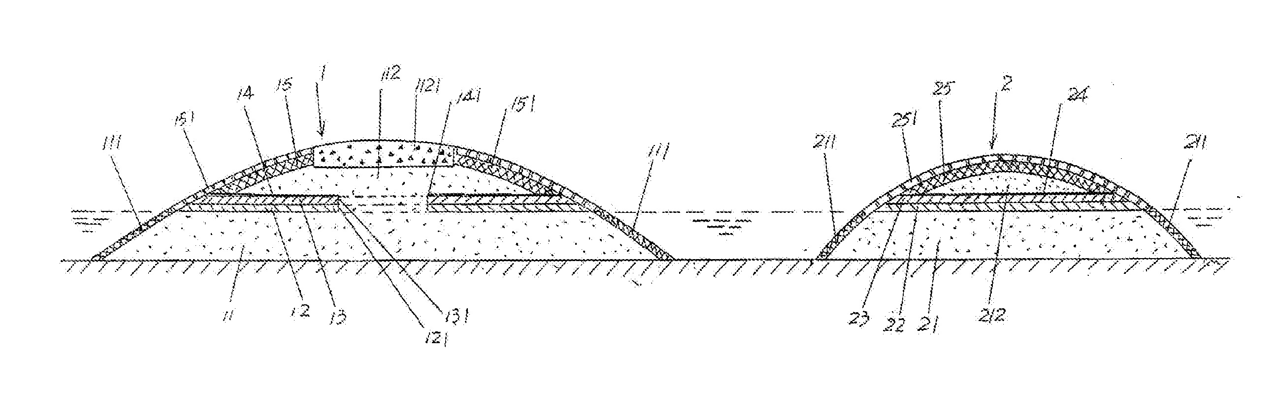
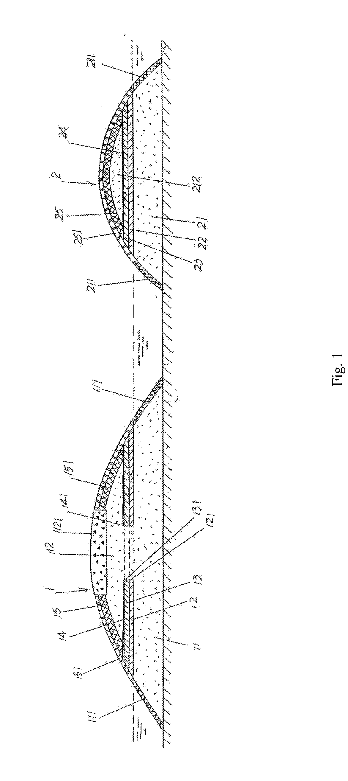
[0026]Referring to the drawing, constructing the in-situ purification island shown in the FIG. 1 comprises the steps as below:

[0027]A) Constructing the upstream purification island main body 1. Before dredging silt and returning water in the river, the first base backfill layer 11 is built by the silt dredged from the river. The upper of the first base backfill layer 11 is parallel to horizontal plane of river water level. The first lower layer 12 is arranged on the upper part of first backfill layer 11. The first hydrophobic layer 13 is arranged on the upper part of the first lower layer 12. The first penetrating water layer 14 is covered on the first hydrophobic layer 13. The first upper layer 15 is arranged on the upper part of the first penetrating water layer 14. The first ecological bags 111 are set around the surface of the first base backfill layer 11. The first lower layer 12 has center formed with a lower filling layer 121. The first hydrophobic layer 13 has center fo...


PUM


Abstract

An in-situ purification island structure and the construction method thereof, which refers to the field of sewage treatment technology. The in-situ purification island structure comprises the upstream purification island main body and the downstream purification island main body, in which the upstream purification island main body comprises the first base backfill layer, the first lower layer, the first hydrophobic layer, the first penetrating water layer and the first upper layer. The first ecological bags are set around the surface of the first base backfill layer. The first lower layer has center formed with a lower filling layer. The first hydrophobic layer has center formed with a hydrophobic filling layer. It has a good natural purifying effect on the sewage, saves the investment and cost, no limitation on the applications, the capacity and efficiency of the purifying is high, and saves the resource.

Description

TECHNICAL FIELD[0001]This present invention refers to the field of sewage treatment technology, and more particularly to an in-situ purification island structure, and the construction method of the in-situ purification island structure.BACKGROUND ART[0002]The concept of the in-situ purification island mentioned above means the facilities to naturally purify the polluted water system of rivers or lakes, constructed with the bed of river or lacustrine as the carrier.[0003]As an important carrier of natural resources and the environment, rivers and lakes have the economic functions as flood controlling and drainage, farm irrigation, water supply, shipping and farming, and the ecological functions as providing habitat and thereby reflecting biodiversity, climate regulation, improvement of the environment, shaping the landscape and water conservation, which has an important realistic and future significance to the rise and fall of the city and the economic development and prosperity.[000...

Claims


Application Information

Patent Timeline
IPC IPC(8): C02F3/32E02F1/00E02B3/02E02B3/12C02F3/30E02B3/18
CPCC02F3/327C02F3/301C02F3/308E02B3/18C02F2103/007E02B3/026E02B3/122E02F1/00E02B3/023C02F3/046E02B3/02Y02A10/30Y02W10/10
Inventor AN, SHUQINGZHOU, LINGYANREN, LIJUNZHANG, YUYUAN
Owner NANJING UNIV ECOLOGICAL RES INST OF CHANGSHU
Why Eureka
Try Eureka