Fiber-optic sensor and method

a fiber optic sensor and fiber optic technology, applied in the field of fiber optic sensors, can solve the problems of inability to correct the wavelength shift due to source aging, and the generality of methods that do not compensate a potential higher order

Inactive Publication Date: 2016-12-29
HITACHI ENERGY SWITZERLAND AG
View PDF21 Cites 11 Cited by
  • Summary
  • Abstract
  • Description
  • Claims
  • Application Information

AI Technical Summary

Benefits of technology

[0040]In other cases, the cross-coupling element can counteract a combination of residual quadratic and linear temperature dependence of the signal. In general, the temperature dependent variation of the signal to-be-compensated can e.g. originate from the temperature dependence of mechanical stress exerted on the sensing element, of bend-induced birefringence in a sensing fiber, of the magneto-optic or electro-optic effect of the sensing element, of the piezo-electric effect of a piezo-electric material attached to the sensing element, of the intrinsic birefringence in the sensing element such as in a spun highly-birefringent optical fiber, of the working point of the sensor, of a retarder or a Faraday rotator in the optical path, or of combinations thereof.

Problems solved by technology

Wavelength shifts due to source aging are not corrected when using these methods.
However, these methods generally do not compensate a potential higher order, in particular second order, i.e. parabolic or quadratic, temperature dependence or can even introduce an additional higher order temperature dependence.

Method used


Image

  • Fiber-optic sensor and method
  • Fiber-optic sensor and method
  • Fiber-optic sensor and method

Examples


Embodiment Construction

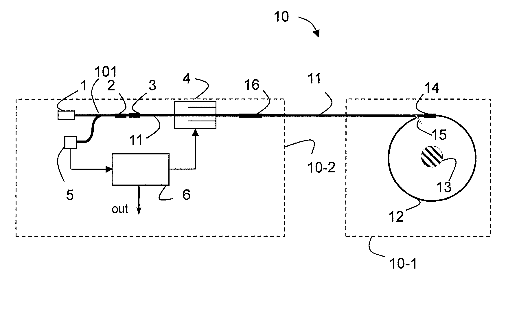
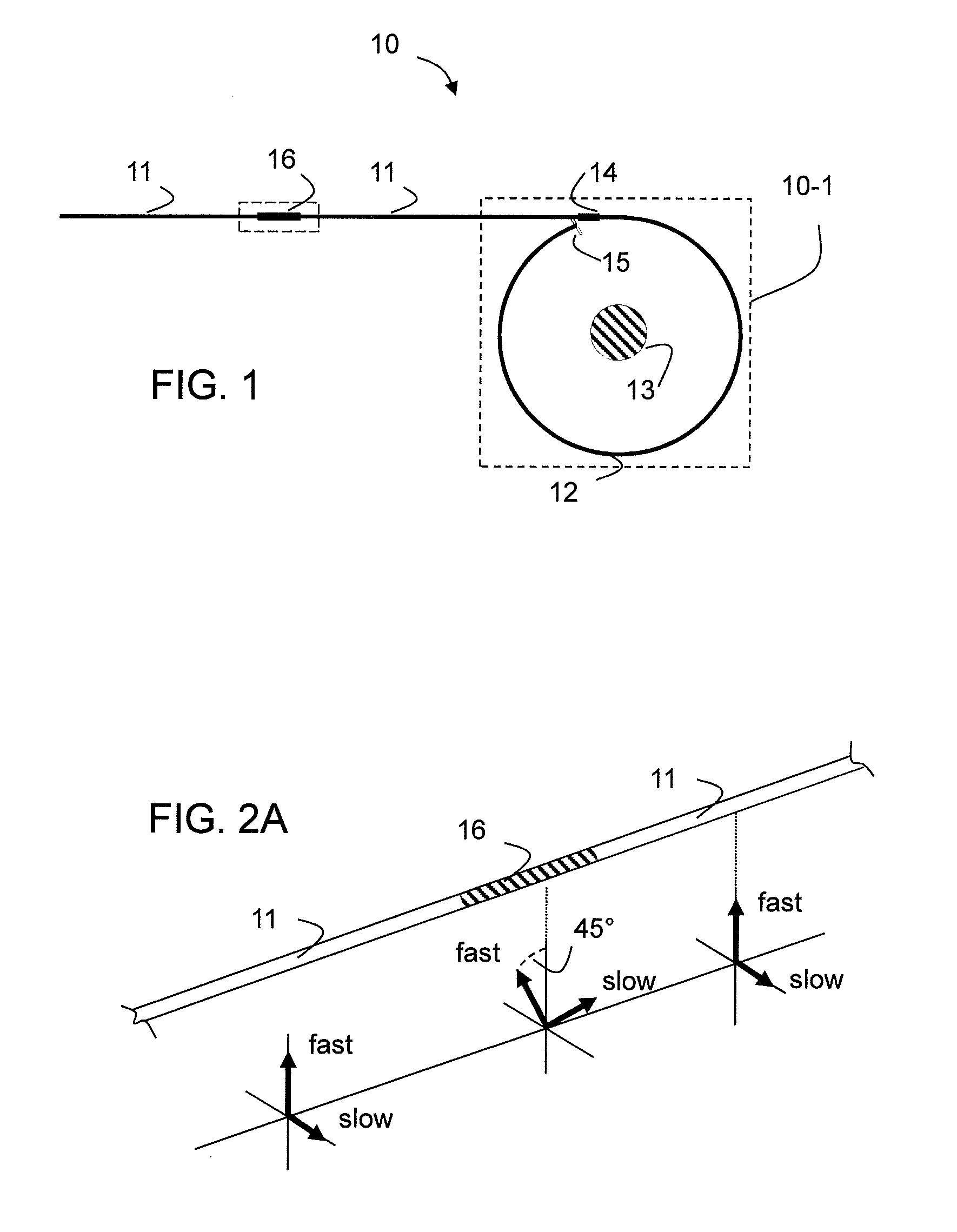
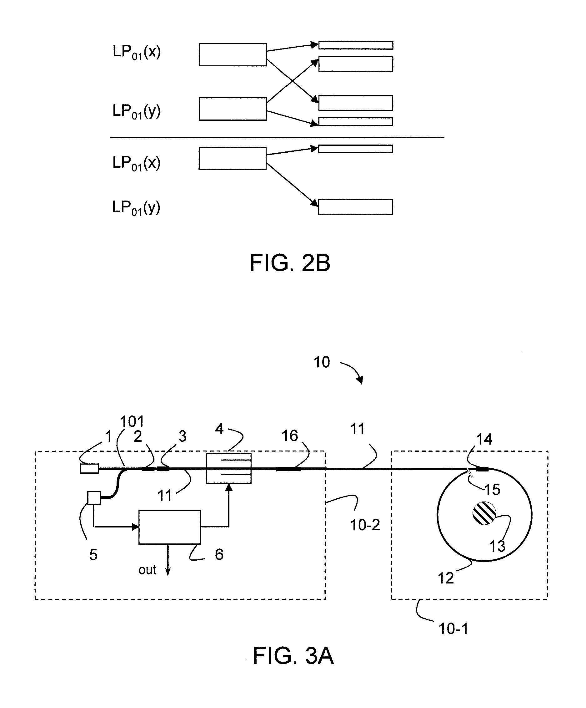
[0058]In FIG. 1 there is shown a general example of the present invention illustrating configurations of the sensor head 10-1 of a reflective fiber-optic current sensor 10 in a schematic manner. In this general example, a polarization maintaining (PM) fiber lead 11 transfers the light into and back from the sensor head which includes a sensing element 12 being in this example a sensing fiber 12 wound in one or more (N) loops around a conductor 13. Depending on the method of measuring the magneto-optic phase shift, either a superposition of light in both of the two orthogonal polarization states of the fundamental PM fiber mode or only light in one polarization state is injected into the sensing fiber element 12.

[0059]Depending on the specific detection technique the linearly polarized light waves may be converted to circular waves before they enter the sensing fiber by using a retarder 14, which in the present example is a fiber-optic QWR (quarter-wave retarder), located at the tran...


PUM


Abstract

A fiber optic sensor and related method are described, with the sensor including a cross-coupling element in the optical path between a polarizing element and a sensing element, but separated from the sensing element itself; with the cross-coupling element generating a defined cross-coupling between the two orthogonal polarization states of the fundamental mode of a polarization maintaining fiber guiding light from the light source to the sensing element thus introducing a wavelength-dependent or temperature-dependent sensor signal shift to balance wavelength-dependent or temperature-dependent signal shifts due to other elements of the sensor, particularly signal shifts due to the wavelength dependence of the Faraday effect or the electro-optic effect constant.

Description

FIELD OF THE INVENTION[0001]The invention relates to a fiber optical sensor such as a fiber-optic current sensor (FOCS) or magnetic field sensor that includes a sensing fiber to be exposed to a magnetic field, e.g. of a current to be measured, or such as a fiber-optic voltage sensor, both typically used in high voltage or high current applications.BACKGROUND OF THE INVENTION[0002]Fiber-optic current sensors rely on the magneto-optic Faraday effect in an optical fiber that is coiled around the current conductor. The current-induced magnetic field generates a circular birefringence in the optical fiber that is proportional to the applied magnetic field. A preferred arrangement employs a reflector at the sensing fiber's far end so that the light coupled into the fiber performs a round trip in the fiber coil. Commonly, left and right circularly polarized light waves, which are generated from two orthogonal linearly polarized light waves by a fiber-optic phase retarder spliced to the sen...

Claims


Application Information

Patent Timeline
Patent Type & Authority Applications(United States)
IPC IPC(8): G01R15/24G01R19/32
CPCG01R15/241G01R19/32G01R15/246G01R15/247
Inventor MULLER, GEORGBOHNERT, KLAUSFRANK, ANDREASGABUS, PHILIPPE
Owner HITACHI ENERGY SWITZERLAND AG
Why Eureka
Try Eureka