Method and a system for reliably starting a turbine engine

a turbine engine and reliable technology, applied in the direction of engine starters, turbine/propulsion engine ignition, machines/engines, etc., can solve the problems of gas generators that accelerate fast, the practicability of implementation is not easy, and the ignition window passes too quickly

Active Publication Date: 2017-01-05
SAFRAN HELICOPTER ENGINES
View PDF4 Cites 17 Cited by
  • Summary
  • Abstract
  • Description
  • Claims
  • Application Information

AI Technical Summary

Benefits of technology

[0048]The invention seeks to remedy the above-mentioned drawbacks and in particular to make it possible to avoid overdimensioning the electrical power supply batteries, while improving the reliability of starting and making ignition and starting of turboshaft engines more robust.
[0051]In a particular embodiment, the DC starter is of the starter-generator type, thus making it possible, above a speed threshold of the gas generator, to switch the starter-generator into generator mode, e.g. so as to power an on-board network of an aircraft in which the turbine engine is installed.
[0072]The invention thus consists in a device under the control of the turboshaft computer that serves to bring the gas generator of the engine up to speed and to maintain it at a constant speed in the ignition window of the engine, so long as the combustion chamber of the engine has not ignited. The main advantage is that the power needed for keeping the gas generator rotating in the ignition window is very low. By way of example, the mechanical power needed for keeping rotation of the gas generator of a helicopter turboshaft engine in its ignition window is of the order of 1 kW to 3 kW, whereas the maximum power developed by the starter during the starting sequence may be as much as 5 kW to 20 kW, i.e. 5 to 7 times greater. The unit based on low power electronics is thus of a size and a cost that are much lower than they would be for an analogous system designed to control the starter over the entire range of starting speeds.
[0073]Once ignition has been detected, the device is shunted and the starter is powered directly from the on-board network of the aircraft, typically at 28 V, without control, the back emf from the already rotating starter at the time of switchover serving to reduce the starting current and to eliminate a large portion of the current peak that is observed when the gas generator is initially stationary.

Problems solved by technology

Nevertheless, practical implementation encounters difficulties that are explained with reference to FIG. 7 together with the following basic equations summarized below for better understanding.
Unfortunately, the power supply voltage (e.g. having a design value of 28 V under nominal conditions) can vary considerably, depending on whether starting is being done from the battery or form a ground power unit.
Consequently, when starting using a ground power unit (rarely standardized, often delivering a voltage that is high), at altitude (with the compressor presenting low opposing torque), or with an engine that is already hot (possessing low friction), it is possible to have a starting torque that is very high—greater than the specified maximum value Cmax—and an opposing torque that is low, leading to the gas generator to accelerate fast so that it passes too quickly through the ignition window.
Another factor that is difficult to take into account is the variable time required for filling fuel into the injection harness associated with the combustion chamber, and this can lead to a delay between the instant at which the valves are opened and the instant at which fuel actually penetrates into the chamber.
Finally, once the starting injectors have ignited, the time required for the flame to propagate to the adjacent injectors is also a phenomenon that is complex and poorly controlled at present, thereby requiring air to flow at a speed that is not too great.
It can thus be seen that a poorly controlled starting torque that might be too high can lead to passing through the ignition window too quickly and to failure to start.
It has been observed that present-day 28 V starter-generators and starters that are not controlled find it difficult to comply with the contradictory specifications for minimum torque and maximum torque in all possible situations.
Nevertheless, the starting resistance serves to reduce acceleration of the gas generator only under circumstances in which the starter torque is too high (high battery voltage, low resistances, hot engine, etc. . . . ).
Under other circumstances, in particular when the opposing torque is high or the power supply voltage is low (cold battery), there is no need to limit starting current, and indeed that might potentially be a handicap.
Furthermore, the starting resistance dissipates a very large amount of power (1 kilowatt (kW) to 3 kW); it is therefore complex to fabricate and it needs to be installed in a location where Joule effect heat losses can easily be discharged without excessively heating the surrounding equipment.
Finally, the energy lost in the resistance leads to overdimensioning the battery.
Furthermore, the problem of accelerating too fast in the ignition window is not handled, since the purpose of that circuit is rather to continue assisting the gas generator to accelerate at high speed (and thus with high back emf) without defluxing the starter.
Such power electronics is thus particularly heavy and expensive.
Under all circumstances, this thus constitutes a solution that is particularly heavy, complex, and expensive.
This constraint, which applies only at low speeds of rotation of the gas generator (less than 15% NG, where NG is the nominal speed of the generator), requires the manufacturer to limit starting torque over the entire range of speeds, and that can be a handicap in situations of starting at very low temperature where the opposing torque from the gas generator is high, the power supply voltage to the starter is low, and ignition is difficult.
The unit based on low power electronics is thus of a size and a cost that are much lower than they would be for an analogous system designed to control the starter over the entire range of starting speeds.

Method used


Image

  • Method and a system for reliably starting a turbine engine
  • Method and a system for reliably starting a turbine engine
  • Method and a system for reliably starting a turbine engine

Examples


Embodiment Construction

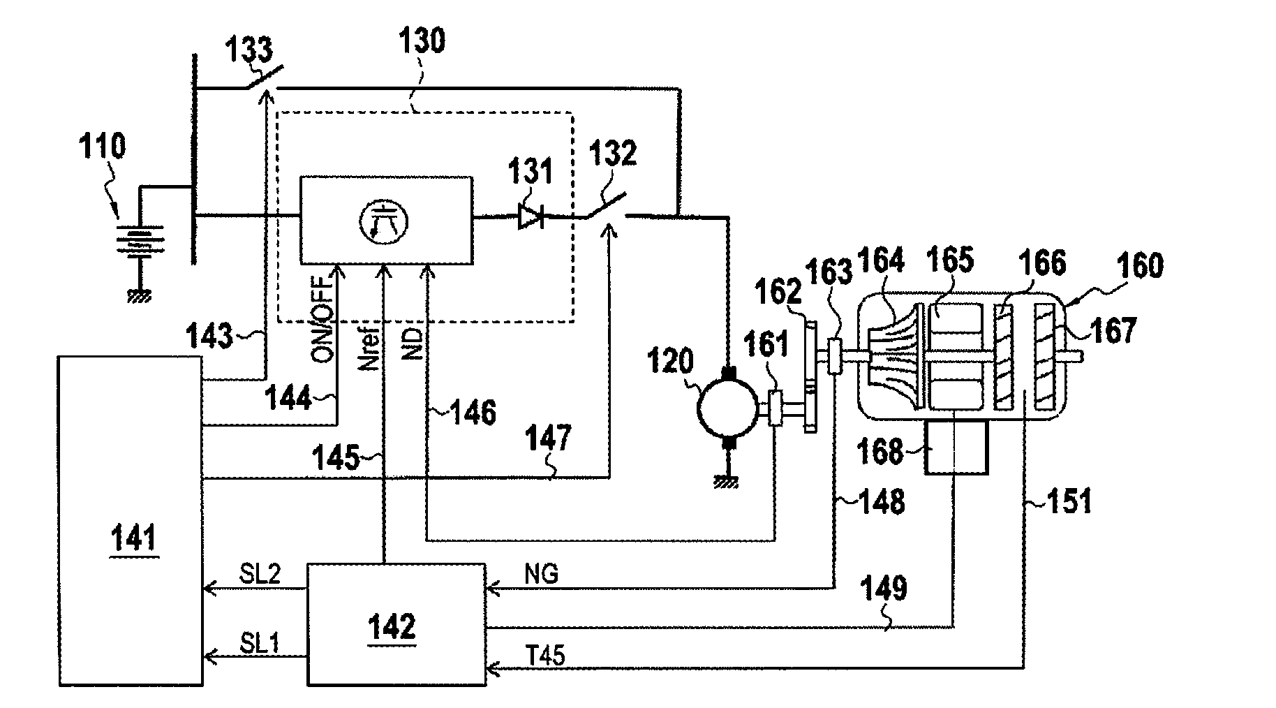
[0087]FIG. 1 is a diagram showing the general configuration of a device of the invention.

[0088]The reliable starter system for a turbine engine comprises a storage battery 110 that may be a single battery or a group of batteries and that may be constituted by the power supply from an on-board network of an aircraft, e.g. 28 V, but the invention is not limited to this voltage.

[0089]A DC starter 120 may be constituted by a simple DC starter or by a starter generator (SG) capable of operating not only in motor mode, but also in generator mode once the starting stage has terminated, e.g. in order to power an on-board network. In the description below, the term “starter” is used to cover both a starter only and / or a starter-generator, unless specified to the contrary.

[0090]The turbine engine starter system includes a transmission gearbox 162 including in particular stepdown gearing for transmitting motion from the starter 120 to the main axis of the engine, and also including auxiliary e...


PUM


Abstract

There is provided a starting system for reliably starting a turbine engine, the system including first and second circuits connected in parallel and arranged between a battery of the engine and a DC starter of the engine, the first circuit including a DC-DC converter connected in series with a first switch and the second circuit including a second switch; a sensor configured to sense a speed of rotation of a compressor of the engine; a sensor configured to sense a temperature at an inlet to a free turbine of the engine; and a control circuit configured to control the first and second switches as a function of information supplied by the sensor configured to sense the speed of rotation of the compressor and by the sensor configured to sense the inlet temperature of the free turbine.

Description

TECHNICAL FIELD AND STATE OF THE PRIOR ART[0001]The invention relates to a method and to a system for reliably starting a turbine engine.[0002]The field of application of the invention is more particularly that of controlling the starting of gas turbine aeroengines such as turboshaft engines for helicopters or turboprops for fixed wing aircraft, or indeed the starting of gas turbine auxiliary power units (APUs) mounted on board aircraft.[0003]Nevertheless, the invention is applicable to other types of turbine engine, e.g. industrial turbines.[0004]In known manner, an aircraft turbine engine comprises a combustion chamber, a compressor shaft having a compressor wheel mounted thereon to feed compressed air to said combustion chamber, and at least one starter or starter-generator connected to said shaft so as to deliver sufficient starting torque thereto for driving it in rotation.[0005]In order to start the turbine engine, the starter begins by accelerating the compressor shaft in a f...

Claims


Application Information

Patent Timeline
Patent Type & Authority Applications(United States)
IPC IPC(8): F02C7/268H02K11/25H02K11/21H02K23/00H02K7/116
CPCF02C7/26F02C7/268F02C7/275Y02T50/60F01D19/00F02N11/08F02N2011/0888F05D2220/323F05D2260/85F05D2270/303F05D2270/304H02K7/116H02K23/00H02K11/21H02K11/25
Inventor POUMAREDE, VINCENTHERRIET, PIERRE
Owner SAFRAN HELICOPTER ENGINES
Why Eureka
Try Eureka