Implantable nerve stimulator having internal electronics without asic and methods of use

a nerve stimulator and internal electronics technology, applied in the field of neurostimulation treatment systems, can solve the problems of difficult to accurately predict or identify specific organs, difficult to determine the viability of treatment, and different outcomes that patients experience, etc., and achieve the effect of reducing the number of components within the ipg, small size, and small siz

Pending Publication Date: 2017-01-12
AXONICS
View PDF1 Cites 4 Cited by
  • Summary
  • Abstract
  • Description
  • Claims
  • Application Information

AI Technical Summary

Benefits of technology

[0007]The present disclosure relates to implantable neurostimulators, and, more specifically, to an implantable pulse generator (IPG). The IPG can include current source/sinks that are configured to selectably source current to, and sink current from, target tissue. This ability of the current source/sinks to selectably source current to and sink current from target tissue decreases the number of components within the IPG and thus enables...

Problems solved by technology

A number of factors may lead to the very different outcomes that patients experience and viability of treatment can be difficult to determine before implantation.
Current stimulation electrode placement/implantation techniques and known treatment setting techniques suffer from significant disadvantages.
The nerve tissue structures of different patients can be quite different, with the locations and branching of nerves that perform specific functions and/or enervate specific organs being challenging to accurately predict or identify.
The electrical properties of the tissue structures surrounding a target nerve structure may also be quite different among different patients, and the neural response to stimulation may be markedly dissimilar, with an electrical stimulation pulse pattern, frequency, and/or voltage that is effective to affect a body function for one patient may impose significant pain on, or have limited effect for, another patient.
Even in patients where implantation of a neurostimulation system provides effective treatment, frequent adjustments and changes to the stimulation protocol are often required ...

Method used


Image

  • Implantable nerve stimulator having internal electronics without asic and methods of use
  • Implantable nerve stimulator having internal electronics without asic and methods of use
  • Implantable nerve stimulator having internal electronics without asic and methods of use

Examples


example embodiments

C. Example Embodiments

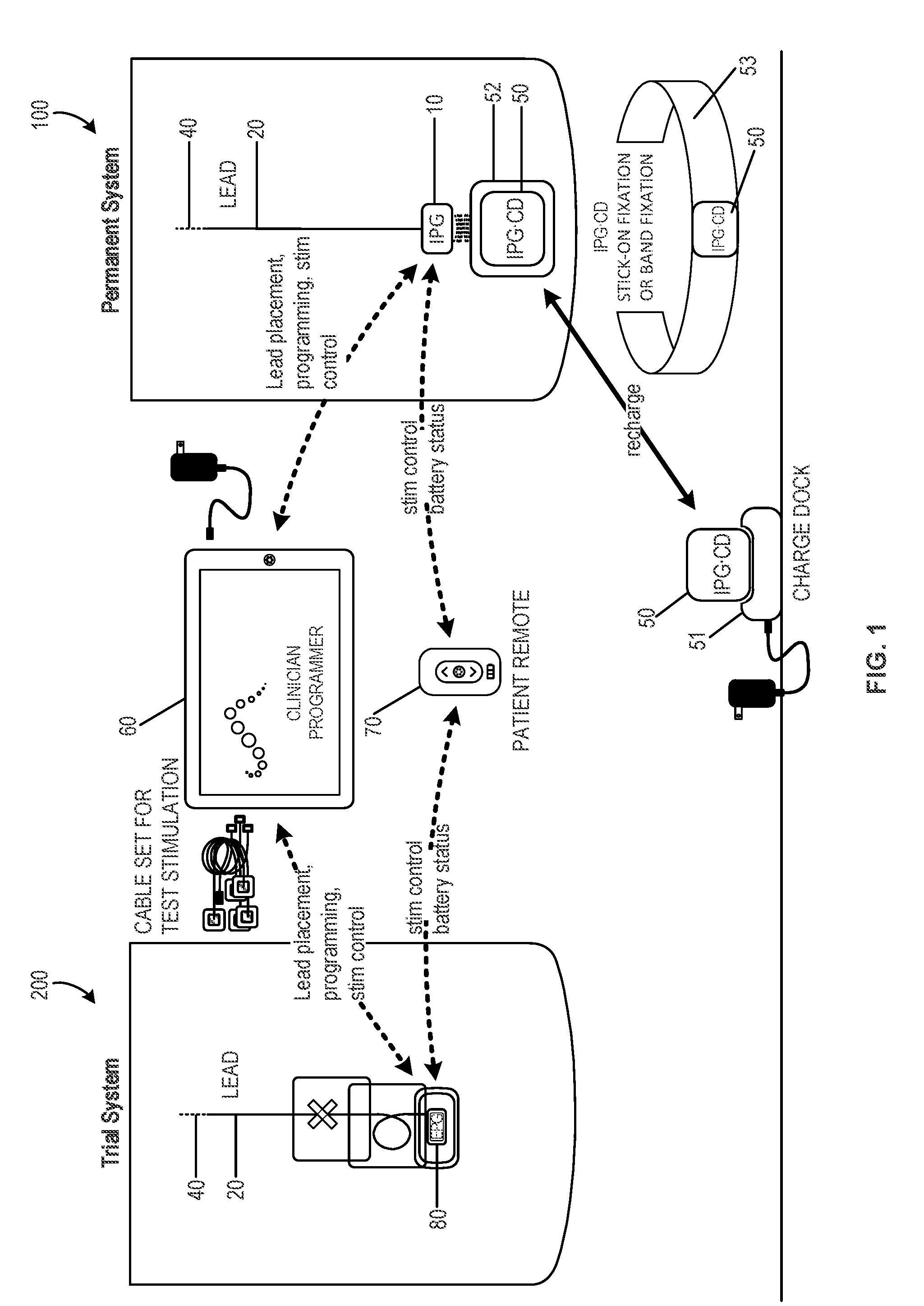
[0055]FIG. 1 schematically illustrates an exemplary nerve stimulation system, which includes both a trial neurostimulation system 200 and a permanently implanted neurostimulation system 100, in accordance with aspects of the invention. The EPG 80 and IPG 10 are each compatible with and wirelessly communicate with a clinician programmer 60 and a patient remote 70, which are used in positioning and / or programming the trial neurostimulation system 200 and / or permanently implanted system 100 after a successful trial. As discussed above, the clinician programmer can include specialized software, specialized hardware, and / or both, to aid in lead placement, programming, re-programming, stimulation control, and / or parameter setting. In addition, each of the IPG and the EPG allows the patient at least some control over stimulation (e.g., initiating a pre-set program, increasing or decreasing stimulation), and / or to monitor battery status with the patient remote. This ap...


PUM


Abstract

An implantable pulse generator that includes a current source/sink generator is disclosed herein. The current source/sink generator includes a current drive differential amplifier. The current driver differential amplifier is configured to selectively source current to, or sink current from a target tissue. The current drive differential amplifier includes an inverting input and a non-inverting input. One of the inputs of the current drive differential amplifier is connected to a virtual ground, and the other is connected to a current command. A stimulation controller can supply a voltage to the other of the inputs of the current drive differential amplifier to select either current sourcing or current sinking.

Description

CROSS-REFERENCES TO RELATED APPLICATIONS[0001]This application claims the benefit of U.S. Provisional Application No. 62 / 191,134, filed Jul. 10, 2015, and entitled “IMPLANTABLE NERVE STIMULATOR HAVING INTERNAL ELECTRONICS WITHOUT ASIC AND METHODS OF USE,” the entirety of which is hereby incorporated by reference herein. The present application is related to U.S. Provisional Patent Application No. 62 / 038,122 [Attorney Docket No. 97672-001000US] filed on Aug. 15, 2014 and entitled “Devices and Methods for Anchoring of Neurostimulation Leads”; 62 / 038,131 [Attorney Docket No. 97672-001100US], filed on Aug. 15, 2014 and entitled “External Pulse Generator Device and Associated Methods for Trial Nerve Stimulation”; 62 / 041,611[Attorney Docket No. 97672-001200US], filed on Aug. 25, 2014 and entitled “Electromyographic Lead Positioning and Stimulation Titration in a Nerve Stimulation System for Treatment of Overactive Bladder, Pain and Other Indicators”; 62 / 110,274 [Attorney Docket No. 97672-...

Claims


Application Information

Patent Timeline
IPC IPC(8): A61N1/36A61N1/378A61N1/05
CPCA61N1/36125A61N1/0551A61N1/3787A61N1/36067A61N1/36071A61N1/36007A61N1/05A61N1/3605A61N1/36128A61N1/375A61N1/3754A61N1/36135
Inventor NASSIF, RABIH
Owner AXONICS
Why Eureka
Try Eureka