

Optical characteristic measurement system and calibration method for optical characteristic measurement system
- Summary
- Abstract
- Description
- Claims
- Application Information
AI Technical Summary
Benefits of technology
Problems solved by technology
Method used
Image

Examples
Embodiment Construction
[0027]An embodiment of the present invention will be described in detail with reference to the drawings. In the drawings, the same or corresponding portions are denoted by the same reference characters, and description thereof will not be repeated.
[0028]
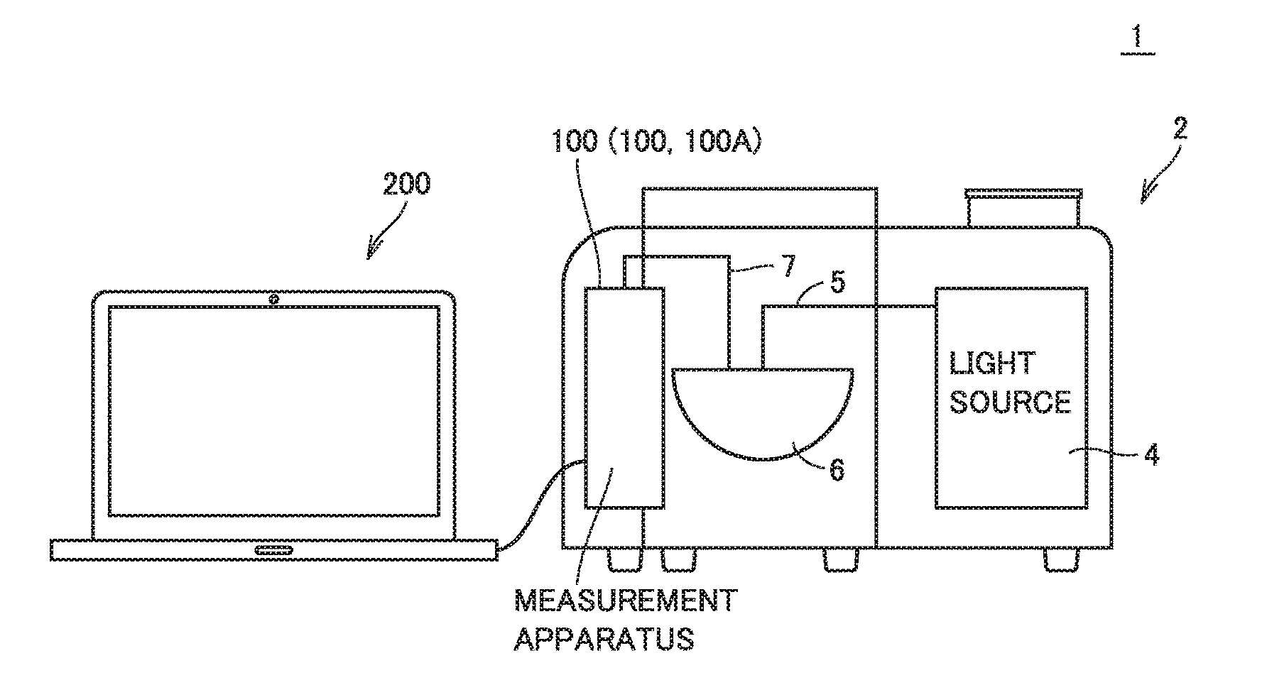
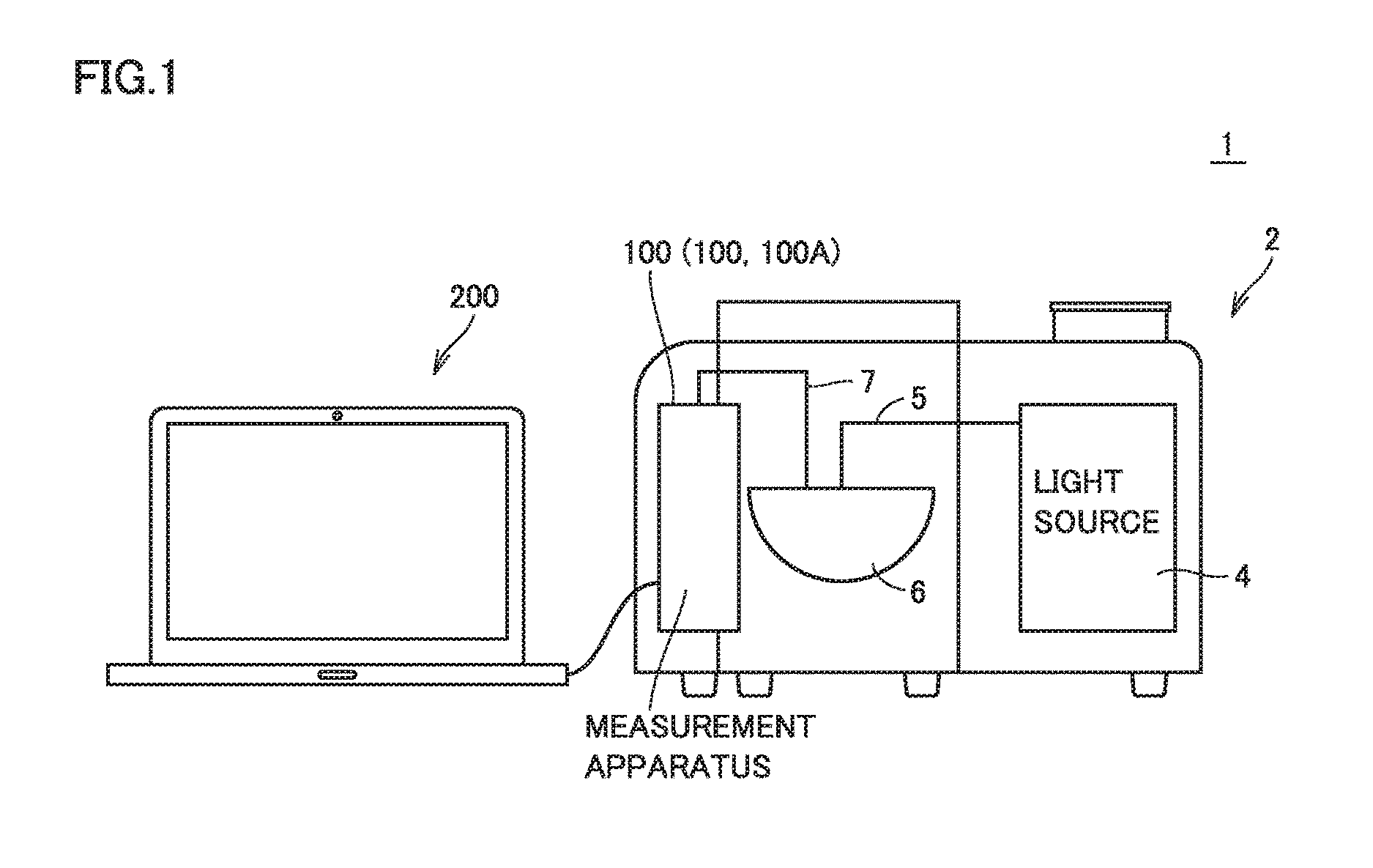
[0029]First, an optical characteristic measurement system 1 including an optical characteristic measurement apparatus (hereinafter also abbreviated as “measurement apparatus”) according to the present embodiment will be described. FIG. 1 is a schematic view showing a configuration example of optical characteristic measurement system 1 including the optical characteristic measurement apparatus according to the present embodiment.
[0030]Referring to FIG. 1, optical characteristic measurement system 1 includes a light source 4, an integrator 6, a system main body 2 that houses a measurement apparatus 100, and a data processing apparatus 200. Although FIG. 1 shows the configuration example in which light source 4, integrator 6 and measure...
PUM
 Abstract
Description
Claims
Application Information