Circuit device, lighting device, and vehicle using the same
- Summary
- Abstract
- Description
- Claims
- Application Information
AI Technical Summary
Benefits of technology
Problems solved by technology
Method used
Image

Examples
embodiment 1
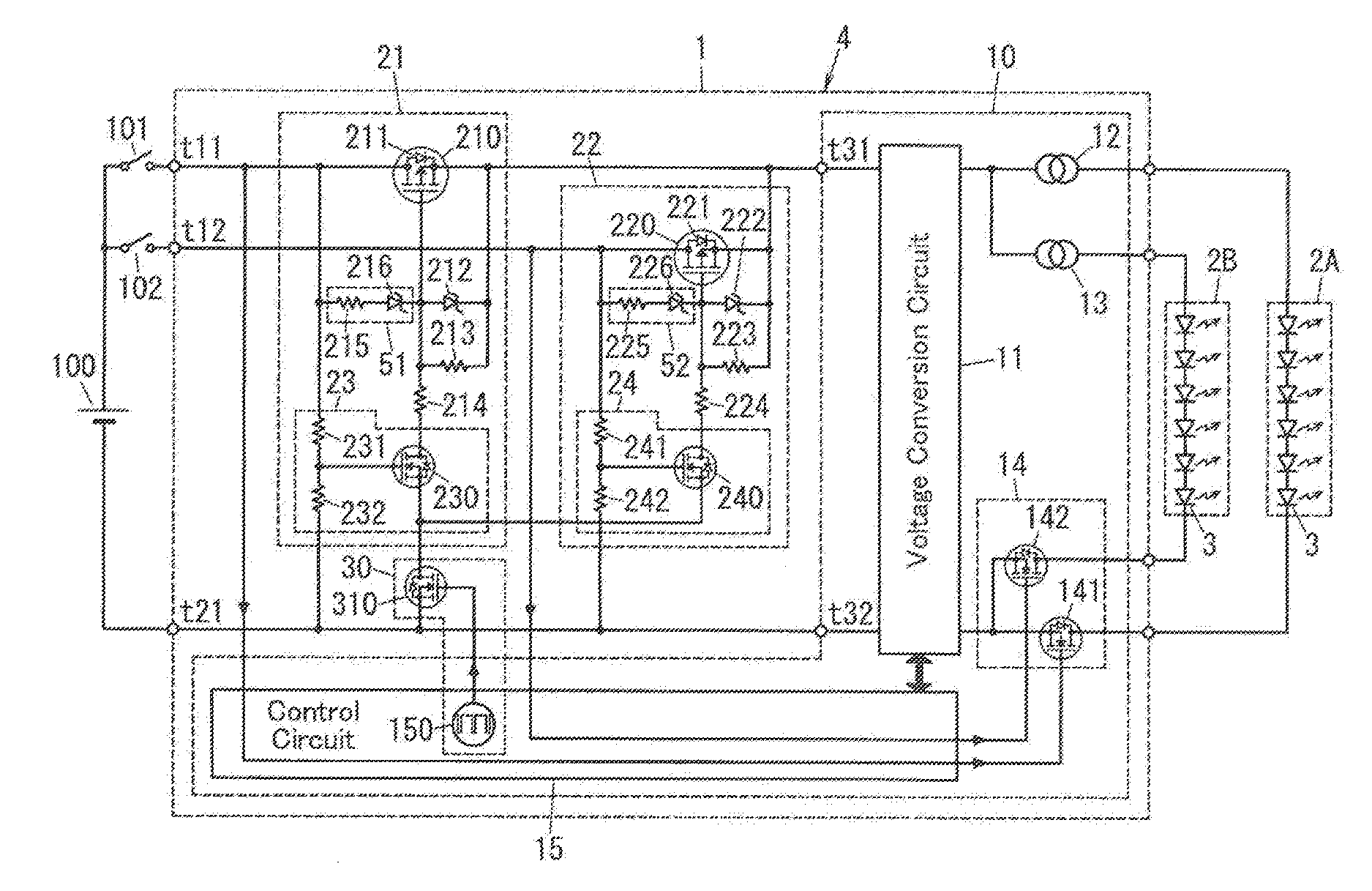
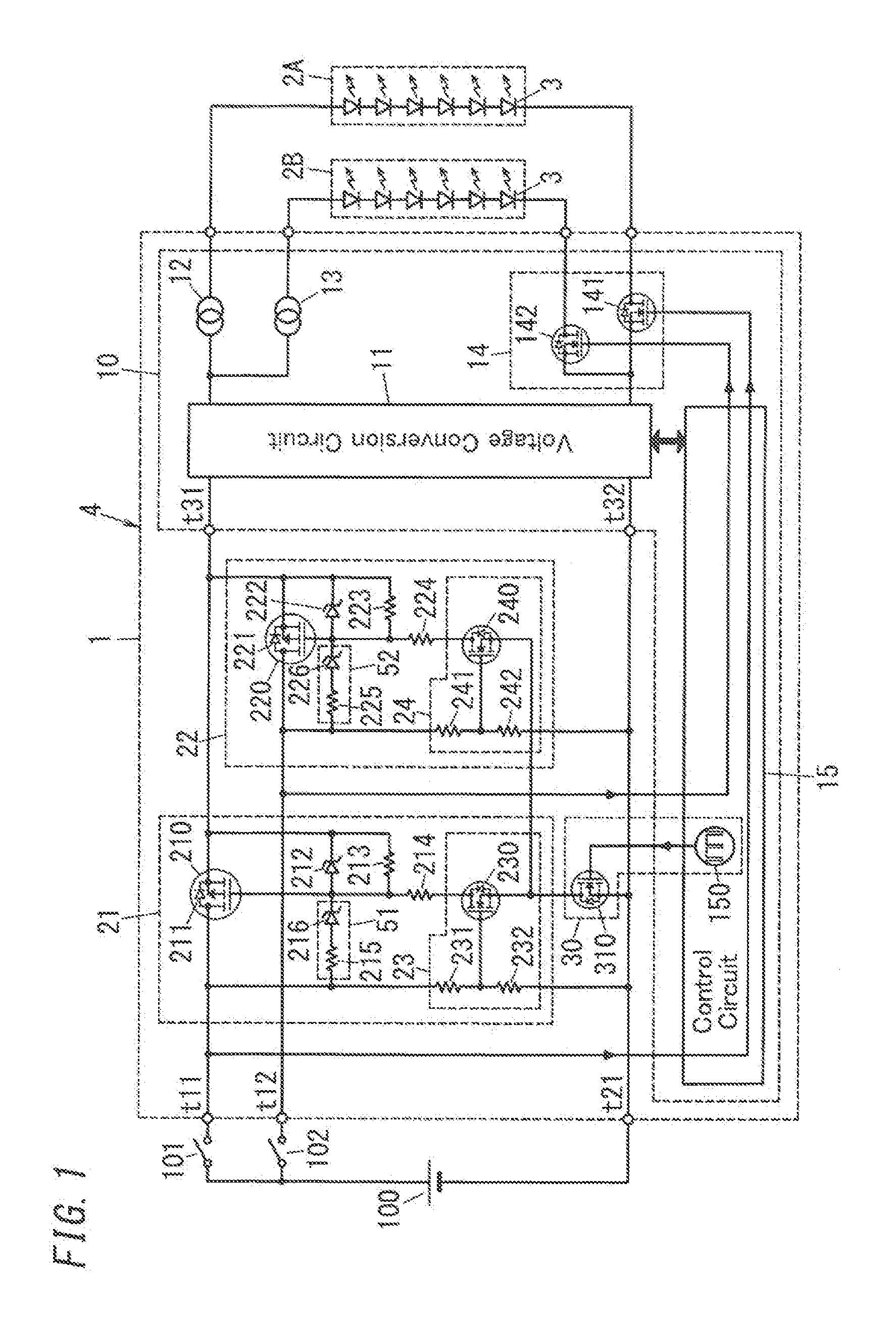
[0021]FIG. 1 is a circuit diagram of a lighting device 4 including a circuit device 1 according to Embodiment 1.
[0022]The circuit device 1 of the present embodiment includes two first power supply connecting terminals t11 and t12, a second power supply connecting terminal t21, a load circuit 10, protection circuits 21 and 22, and a reset circuit 30.
[0023]The circuit device 1 of the present embodiment is included in the lighting device 4 that lights light source blocks 2A and 2B with electric power supplied from a DC power supply 100. The examples of the DC power supply 100 are a battery and a DC power supply circuit that rectifiers and smooths an AC voltage applied by an AC power supply and converts the AC voltage into a DC voltage. Each of the light source blocks 2A and 2B includes a plurality of LED (Light Emitting Diode) 3 that are connected in series to each other. Note that, each of the light source blocks 2A and 2B is not limited to including LEDs as the light source, and may ...
embodiment 2
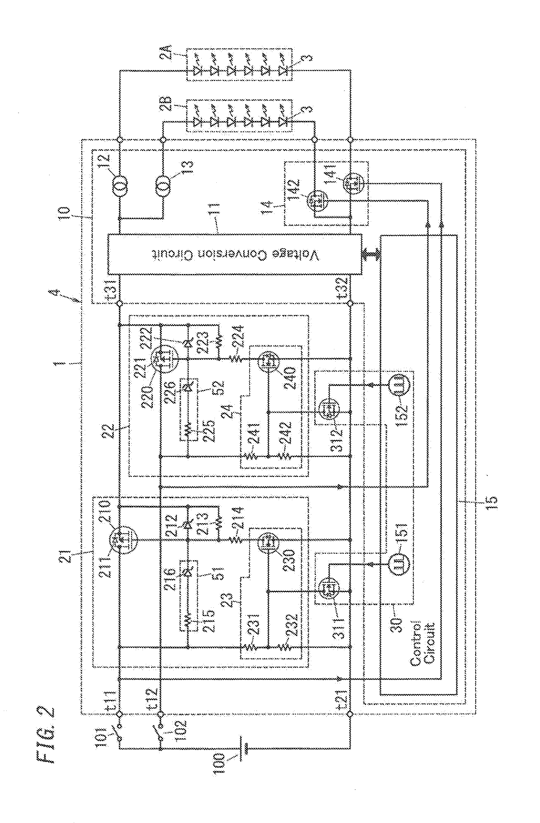
[0083]FIG. 4 is a circuit diagram of a lighting device 4 that includes a circuit device 1 of Embodiment 2. Note that circuit configurations other than a voltage conversion circuit 11, a control circuit 15, protection circuits 21 and 22, and an auxiliary power circuit 41 are the same as those of the circuit device 1 of Embodiment 1. Thus, further description of same components is omitted for sake of brevity.
[0084]The voltage conversion circuit 11 is a switching power supply circuit such as a fly-back converter, and includes a capacitor 111, a transformer 112, a switching element 113, a diode 114, and a capacitor 115. The capacitor 111 is electrically connected between a first input terminal t31 and a second input terminal t32. A primary winding of the transformer 112 and the switching element 113 are connected in series to each other between both ends of the capacitor 111. The switching element 113 includes an N-channel MOSFET, and a drain electrode of the switching element 113 is co...
embodiment 3
[0115]FIG. 6 is a schematic configuration view of an illumination device (fixture) 200 into which a lighting device 4 including the circuit device 1 of Embodiment 1 or 2 is assembled.
[0116]The illumination device 200 of the present embodiment is, for example, a headlight device included in a vehicle 300, and FIG. 7 is an external view of the vehicle 300 in which the illumination device 200 is positioned on a vehicle body 301.
[0117]The case 201 of the illumination device 200 includes a box-shaped body 202 in which one surface is opened, and a translucent cover 203 disposed in an opening of the body 202. Two light source blocks 2A and 2B are accommodated in the body 202. In the light source blocks 2A and 2B, for example, the light source block 2A is a light source for main-beam headlight (high beam), and the light source block 2B is a light source for dipped-beam headlight (low beam). The light source blocks 2A and 2B are respectively amounted on heat radiation structures 204 and 205,...
PUM
 Abstract
Description
Claims
Application Information
 - R&D
- Intellectual Property
- Life Sciences
- Materials
- Tech Scout
- Unparalleled Data Quality
- Higher Quality Content
- 60% Fewer Hallucinations
Browse by: Latest US Patents, China's latest patents, Technical Efficacy Thesaurus, Application Domain, Technology Topic, Popular Technical Reports.
© 2025 PatSnap. All rights reserved.Legal|Privacy policy|Modern Slavery Act Transparency Statement|Sitemap|About US| Contact US: help@patsnap.com