System and method for the direct calorimetric measurement of laser absorptivity of materials

a laser absorptivity and calorimetric measurement technology, applied in the direction of calorimeters, instruments, thermal analysis of materials, etc., can solve problems such as reflected light, and achieve the effect of removing the effect of convective and radiative loss

Active Publication Date: 2017-01-19
LAWRENCE LIVERMORE NAT SECURITY LLC
View PDF9 Cites 4 Cited by
  • Summary
  • Abstract
  • Description
  • Claims
  • Application Information

AI Technical Summary

Benefits of technology

[0009]The present invention is generally directed to a system and method for the direct calorimetric measurement of powder absorptivity, and which eliminates the effect of convective and radiative loss. Generally, a thin and flat homogeneous material is provided and thermally isolated. The material may be a powder, liquid, or solid (i.e. bulk solid). In the case of measuring powders or liquids for absorptivity, a flat container or tray (e.g. disc-shaped container) having a shallow container volume is provided and filled with powder or liquid to produce a thin layer of powder or liquid in the container volume. Dimensioned in this manner, the materials dimensions as well as the porosity are be predetermined and known based on the filled-to-capacity container volume and a measured weight of the material filling the container volume. The material is also thermally isolated by various methods. The material is then uniformly irradiated by laser or diode ar

Problems solved by technology

2000), measure the reflected light from the powder with th

Method used


Image

  • System and method for the direct calorimetric measurement of laser absorptivity of materials
  • System and method for the direct calorimetric measurement of laser absorptivity of materials
  • System and method for the direct calorimetric measurement of laser absorptivity of materials

Examples


Embodiment Construction

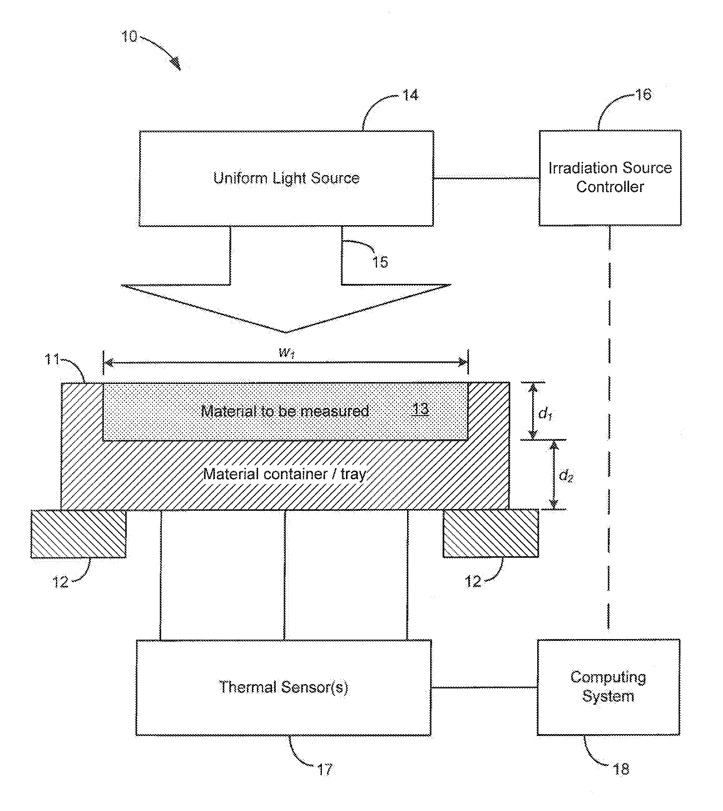
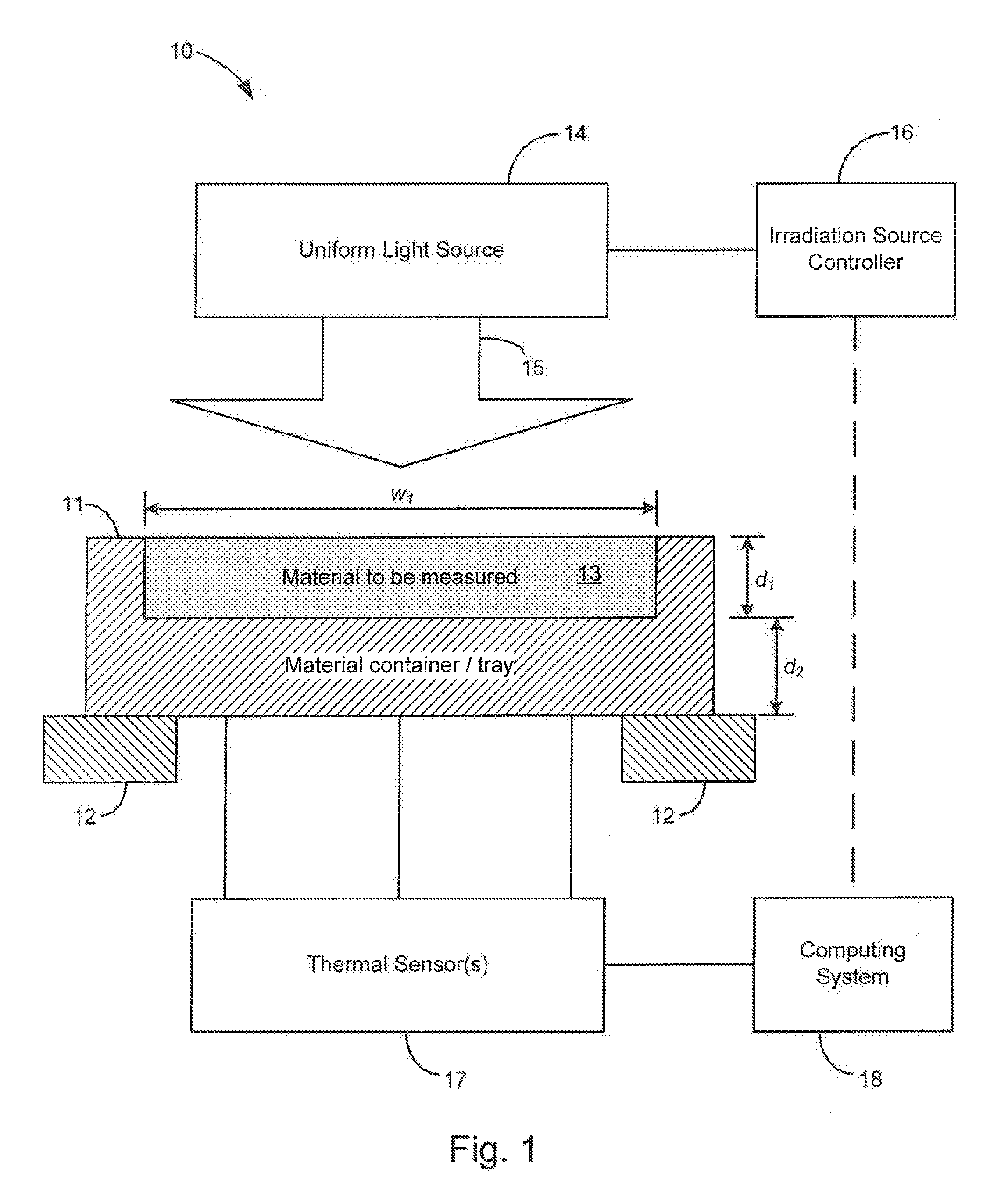
[0013]Turning now to the drawings, FIG. 1 shows an example embodiment of the system for the direct calorimetric measurement of the laser absorptivity of a material of the present invention, generally indicated at 10. The system is shown having a material container or tray 11 having an open cavity for receiving a material to be measured (shown at 13 filling the cavity). The open cavity is shown having a width w1 and a depth d1, and the material container / tray is shown having a thickness d2 between the material to be measured and an outer surface where thermal sensors 17 are shown positioned at various locations to determine temperature and temperature uniformity of the material container / tray. The container is also shown supported by a thermal isolation structure, generally shown at 12. The container 11 and the thermal isolation structure 12 may be characterized together as a material holder adapted to support and thermally isolate the material to be measured. It is appreciated that ...


PUM


Abstract

A method and system for calorimetrically measuring the temperature-dependent absorptivity of a homogeneous material dimensioned to be thin and flat with a predetermined uniform thickness and a predetermined porosity. The system includes a material holder adapted to support and thermally isolate the material to be measured, an irradiation source adapted to uniformly irradiate the material with a beam of electromagnetic radiation, and an irradiation source controller adapted to control the irradiation source to uniformly heat the material during a heating period, followed by a cooling period when the material is not irradiated. A thermal sensor measures temperature of the material during the heating and cooling periods, and a computing system first calculates temperature-dependent convective and radiative thermal losses of the material based on the measured temperature of the material during the cooling period when beam intensity is zero, followed by calculation of the temperature-dependent absorptivity of the material based on the temperature-dependent convective and radiative thermal losses determined from the cooling period.

Description

FEDERALLY SPONSORED RESEARCH OR DEVELOPMENT[0001]The United States Government has rights in this invention pursuant to Contract No. DE-AC52-07NA27344 between the United States Department of Energy and Lawrence Livermore National Security, LLC for the operation of Lawrence Livermore National Laboratory.BACKGROUND[0002]Additive manufacturing is a rapidly growing field with a wide range of applications. Presently, there exists a need for the measurement of powder absorptivity for use in the analysis and modeling of laser-material interactions in the additive manufacturing build process. The absorptivity of powder depends not only on material type and laser wavelength; it is sensitive to the size distribution of the particles, particle shape, powder thickness and porosity.[0003]Existing systems, such as for example the system described in Absorptance of powder materials suitable for laser sintering by N. Tolochko et al, (Rapid Prototyping Journal 6.155. 2000), measure the reflected ligh...

Claims


Application Information

Patent Timeline
IPC IPC(8): G01N25/20
CPCG01N25/20G01K17/00G01K17/04G01N25/48G01N25/4846G01N25/4853G01N25/486
Inventor RUBENCHIK, ALEXANDERGOLOSKER, LLYA V.LEBLANC, MARY M.MITCHELL, SCOTT C.WU, SHELDON S.
Owner LAWRENCE LIVERMORE NAT SECURITY LLC
Why Eureka
Try Eureka