
Apparatus for combining optical radiation

a technology of optical radiation and apparatus, applied in the direction of optical elements, instruments, optical waveguide light guides, etc., can solve the problems of polymer coating being a source of unreliability, and expensive implementation methods, etc., to reduce or eliminate damage to the polymer coating

Active Publication Date: 2017-01-19
SPI LASERS UK
View PDF7 Cites 33 Cited by
  • Summary
  • Abstract
  • Description
  • Claims
  • Application Information

AI Technical Summary

Benefits of technology

The present invention provides an apparatus for combining optical radiation that reduces or eliminates damage to the polymer coating on the output optical fibre caused by higher angle rays. This is important for optical fibre lasers and amplifiers that have powers greater than around (100 W). The apparatus includes a taper formed from glass, an output optical fibre, and a polymer coating. A cladding mode stripper is positioned at a specific location along the taper to attenuate higher angle rays. The apparatus can be assembled with adhesive, but it is important to ensure the thermal handling capability of the adhesive does not limit the power handling of the combiner.

Problems solved by technology

However, this polymer coating is a source of unreliability as it can overheat if subjected to pump radiation that exceeds the numerical aperture of the fibre.
This method of removing unwanted light is complex and expensive to implement.
The multimode combiner, however, is based on polymeric materials which have associated reliability concerns owing to poor thermal properties.
These polymers can degrade if optical power leaks from the glass fibre into the coating.
This is generally undesirable as it contributes to an increase in the divergence of the output.
For this reason, the thickness of the outer capillary is kept to a minimum, which leads to practical difficulties when assembling such a combiner.
Depending on the value of N, this can be complex to achieve.
The thermal handling capability of this adhesive can limit the power handling of the combiner.

Method used


Image

  • Apparatus for combining optical radiation
  • Apparatus for combining optical radiation
  • Apparatus for combining optical radiation

Examples


Embodiment Construction

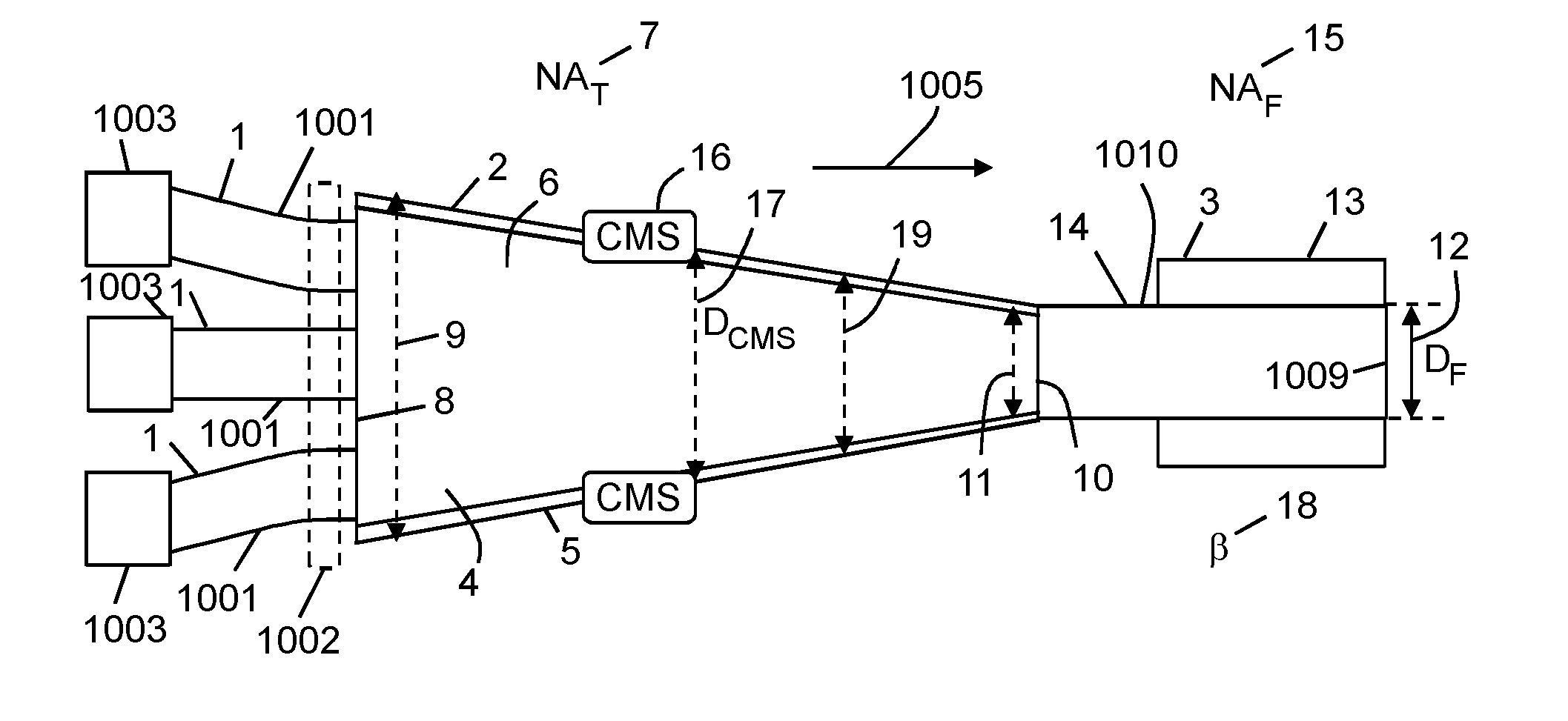
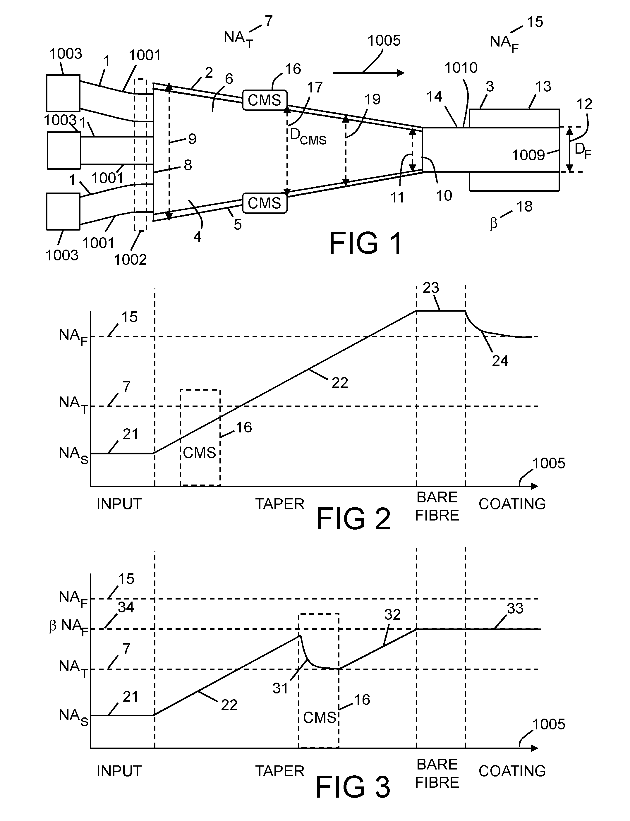
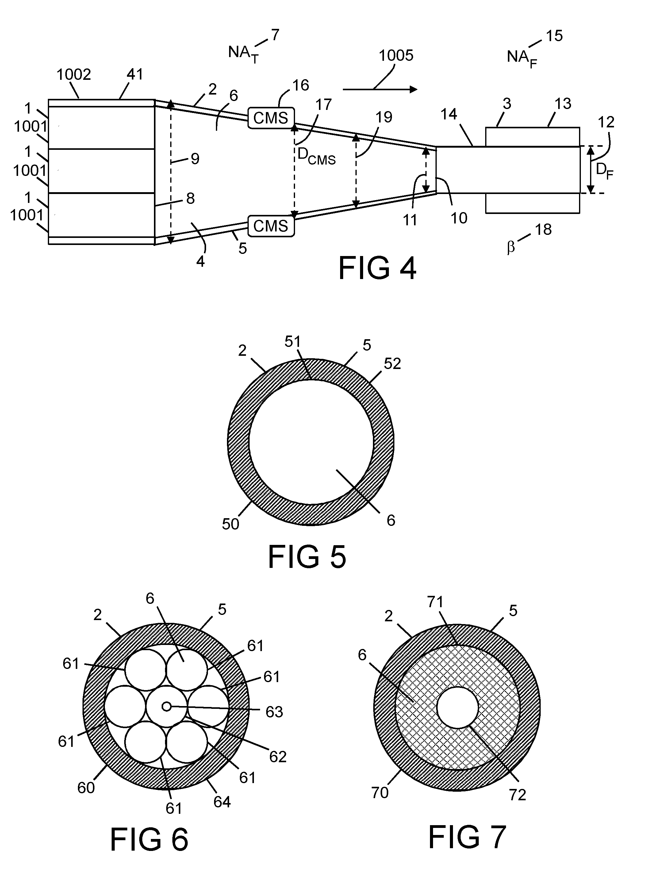
[0069]With reference to FIG. 1, there is provided apparatus for combining optical radiation, which apparatus comprises a plurality of inputs 1, a taper 2 formed from glass 6, and an output optical fibre 3, wherein: the taper 2 comprises a waveguide 4 having a glass outer cladding 5, which waveguide 4 is defined by a numerical aperture NAT 7; the taper 2 has a first end 8 having a first diameter 9, and a second end 10 having a second diameter 11; the first diameter 9 is greater than the second diameter 11; the plurality of inputs 1 are coupled to the first end 8;

[0070]the second end 10 is coupled to the output optical fibre 3; the output optical fibre 3 is defined by a fibre diameter DF 12; the output optical fibre 3 comprises a polymer coating 13; the output optical fibre 3 is defined by a numerical aperture NAF 15; the apparatus being characterized in that: the taper 2 comprises a cladding mode stripper 16 located at a diameter DCMS 17 equal to a fraction, the numerator of which is...


PUM


Abstract

An apparatus for combining optical radiation, wherein the apparatus comprises a bundle of input optical fibres formed of glass, a taper, and an output optical fibre, wherein the taper is fused to the output optical fibre; and the apparatus comprises at least one cladding mode stripper to strip out higher order modes that would otherwise degrade a polymer coating on at least one of the input optical fibres and the output optical fibre.

Description

[0001]This application claims priority under 35 U.S.C. §119 to United Kingdom Patent Application No. 1512610.5 filed on Jul. 17, 2015.FIELD OF INVENTION[0002]This invention relates to apparatus for combining optical radiation. The invention has particular relevance for pumping high power optical lasers and amplifiers.BACKGROUND TO THE INVENTION[0003]High power fibre lasers require multi-mode pump combiners to couple pump radiation from multiple high power fibre-coupled diodes into the cladding of rare-earth-doped gain fibres, either directly, or via an intermediate fibre. These fibres are often coated with a polymer coating which acts as a cladding for the pump radiation to be guided against. However, this polymer coating is a source of unreliability as it can overheat if subjected to pump radiation that exceeds the numerical aperture of the fibre.[0004]It would be advantageous if there were a high power combiner in which light with a high numerical aperture could be removed from li...

Claims


Application Information

Patent Timeline
IPC IPC(8): G02B6/28H01S3/094G02B6/14
CPCG02B6/2856G02B6/14H01S3/094057H01S3/094053H01S3/094069G02B6/2835H01S3/094007G02B6/305G02B6/4296H01S3/06745G02B6/266G02B6/2552
Inventor BOTHEROYD, IAIN
Owner SPI LASERS UK
Learn More