
Heat exchanger, particularly for a motor vehicle

a technology of heat exchanger and motor vehicle, which is applied in the direction of electrochemical generators, lighting and heating apparatus, batteries, etc., can solve the problems of reducing the range of vehicles, reducing the efficiency of battery cells, and cells generating nigh power loss, so as to achieve the effect of easy production

Inactive Publication Date: 2017-01-19
MAHLE INT GMBH
View PDF13 Cites 20 Cited by
  • Summary
  • Abstract
  • Description
  • Claims
  • Application Information

AI Technical Summary

Benefits of technology

This patent is about a heat exchanger that uses modules with fluid-connecting elements to cool and heat components. These modules can be stacked and held together by a retaining device, making it easy to produce different heat exchangers with different power classes and thermal output. The use of modules simplifies the mounting process and reduces production costs.

Problems solved by technology

Inefficient heating and cooling in electric vehicles operated by high-performance batteries may result, for example, in a very significant reduction in the range of the vehicle.
On the one hand, below a suitable operating temperature the efficiency of the battery cells is reduced very considerably and the cells generate a nigh power loss.
On the other hand, above a suitable operating range processes take place within the cells which lead to irreversible damage.
With the layered construction of this heat exchanger, it is a drawback that during switching processes, for example when switching a battery cooling circuit on and off, peaks are produced in the air outlet temperature.
Furthermore, this embodiment results in a space-saving arrangement of the first and second components.

Method used


Image

  • Heat exchanger, particularly for a motor vehicle
  • Heat exchanger, particularly for a motor vehicle
  • Heat exchanger, particularly for a motor vehicle

Examples


Embodiment Construction

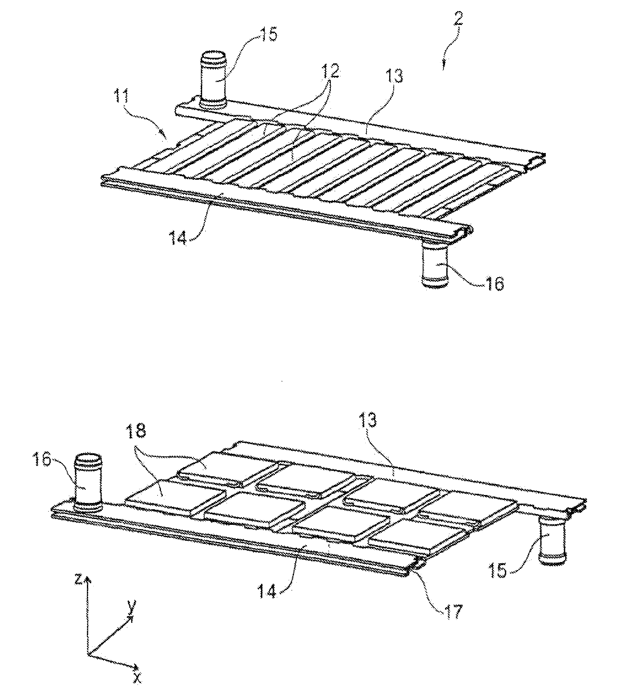
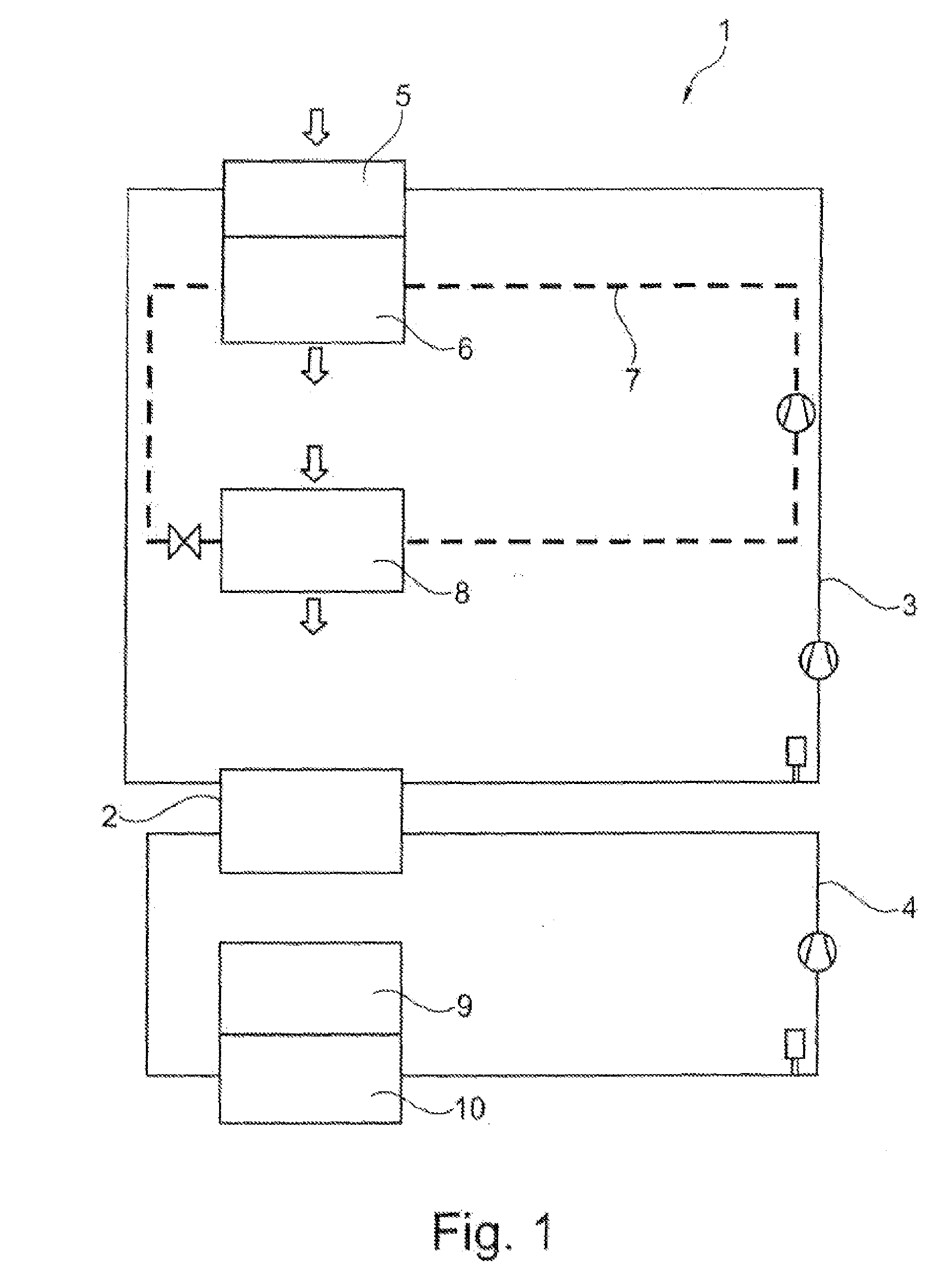
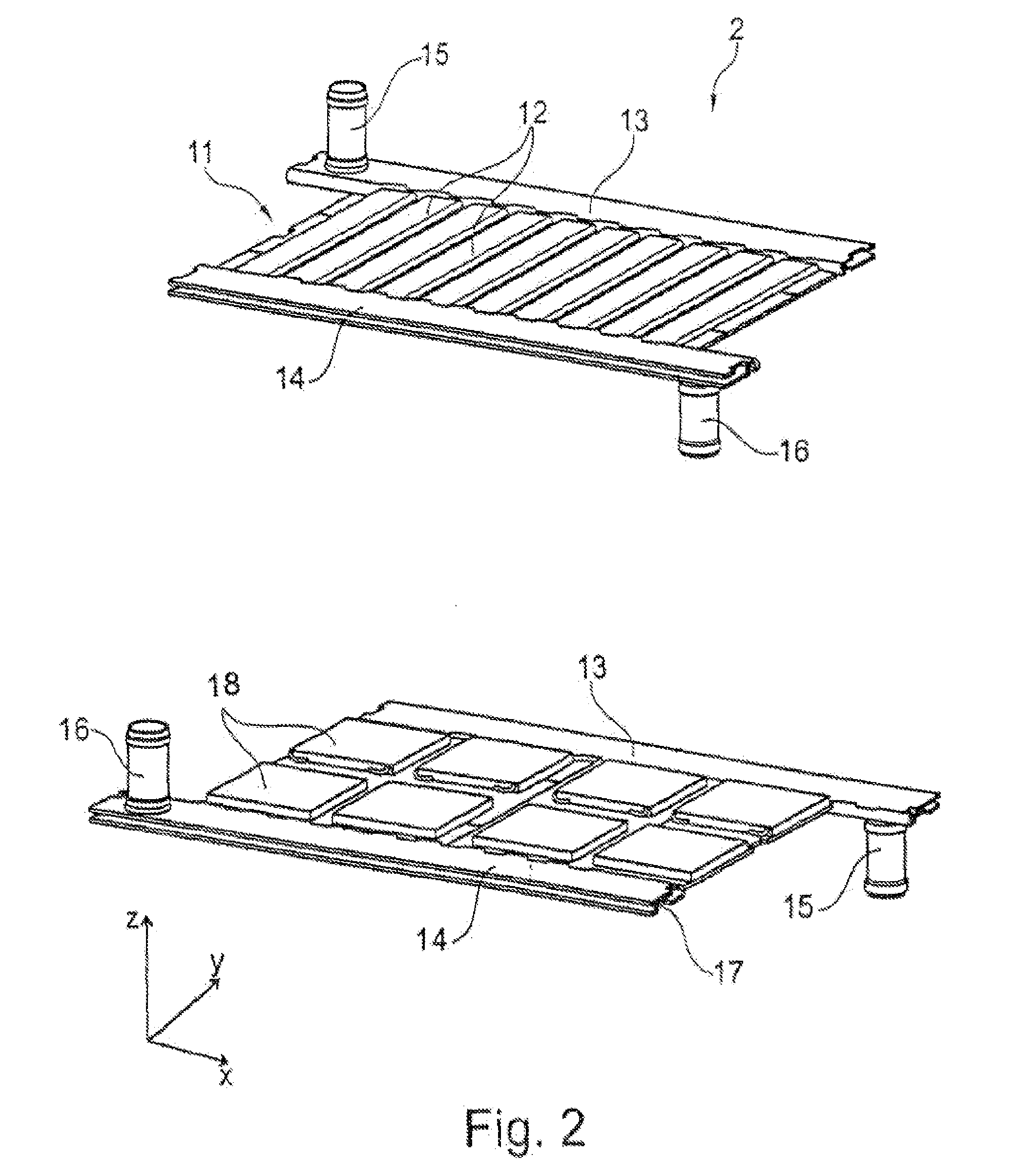
[0033]FIG. 1 shows a first exemplary embodiment of a heat exchanger system 1 comprising the thermoelectric heat exchanger 2 according to the invention. The heat exchanger 2 is configured as a coolant / coolant-temperature control unit with thermoelectrics and is arranged between two cooling circuits, namely the primary circuit 3 and the secondary circuit 4. In this case a first fluid configured as coolant flows through the primary circuit 3, whilst a second fluid also configured as coolant flows through the secondary circuit 4. A low temperature radiator 5 is incorporated in the primary circuit 3 in addition to the heat exchanger 2, said low temperature radiator acting via a capacitor 6 on an air-conditioning circuit 7 within a motor vehicle. An air-conditioning evaporator 8 is arranged at the same time in the air-conditioning circuit 7, a vehicle interior being able to be cooled or heated thereby. The temperature of a high voltage battery 9 arranged in the motor vehicle is controlled...


PUM

PropertyMeasurementUnit
temperatureaaaaaaaaaa
thermoelectricaaaaaaaaaa
Energy efficiencyaaaaaaaaaa

Abstract

The invention relates to a heat exchanger, particularly for a motor vehicle, comprising a first component with a first duct, a second component with a second duct and a thermoelectric element for generating a heat flow, wherein a first fluid of a first fluid circuit can be caused to flow through the first duct to control the temperature of a first external component, wherein a second fluid of a second fluid circuit can be caused to flow through the second duct, which is fluidically separated from the first duct, to control the temperature of a second external component, and wherein the at least one thermoelectric element is arranged between the first and second components, contacting same thermally.

Description

TECHNICAL FIELD[0001]The invention relates to a heat exchanger, particularly for a motor vehicle, as claimed in the preamble of claim 1.PRIOR ART[0002]Energy efficiency plays an important role within the context of the increasing electrification of motor vehicles, in particular with regard to heating and cooling tasks in the motor vehicle. Inefficient heating and cooling in electric vehicles operated by high-performance batteries may result, for example, in a very significant reduction in the range of the vehicle.[0003]With the use of modern high-performance batteries which are constructed from a number of individual cells, such as for example in electric or hybrid vehicles, the temperature of the high-performance battery during operation of the motor vehicle has to be within a specific range in order to ensure the efficiency, functional capability and safety of the motor vehicle. On the one hand, below a suitable operating temperature the efficiency of the battery cells is reduced ...

Claims


Application Information

Patent Timeline
Patent Type & Authority Applications(United States)
IPC IPC(8): H01M10/6572H01M10/625H01L35/30B60H1/00B60H1/14H10N10/13
CPCH01M10/6572B60H1/00478B60H1/143H01M2220/20H01L35/30H01M10/625B60H1/00278F28F3/08F25B21/04F25B2321/0252F28F3/12F28D7/0025B60H2001/2271B60H2001/2275F28D2021/008Y02E60/10H10N10/13
Inventor GRUNWALD, JURGENMOLDOVAN, FLORINWEHOWSKI, MANUEL
Owner MAHLE INT GMBH
Learn More