Locally Enhanced Direct Liquid Cooling System for High Power Applications

a liquid cooling system and high-power technology, applied in the direction of cooling/ventilation/heating modifications, basic electric elements, conduction heat transfer modifications, etc., can solve the problems of increasing the challenge of designing a compact cooling system, high-power semiconductor chips, igbt) generate substantial amount of heat, etc., to effectively dissipate heat generated, enhance turbulent flow, and enhance heat generation

Active Publication Date: 2017-01-19
HONG KONG APPLIED SCI & TECH RES INST
View PDF8 Cites 3 Cited by
  • Summary
  • Abstract
  • Description
  • Claims
  • Application Information

AI Technical Summary

Benefits of technology

[0016]In another aspect of the present invention, an electronic apparatus is disclosed. The electronic apparatus comprises at least one electronic module wherein the electronic module comprises at least one electronic component that generates heat, and a cooling assembly. The cooling assembly has a receiving area on a first surface of a first plate that is adapted to receive at least one electronic module. A heat spreader that has an inner surface and at least one outer surface is disposed inside the cooling assembly. The inner surface of the heat spreader is affixed to a second surface of the first plate adjacently opposite to the receiving area to conductively dissipate heat generated from the at least one electronic component. A plurality of heat dissipating fins that are spaced apart from each other is also disposed inside the cooling assembly. Each heat dissipating fin is coupled to a second plate and extending transversely therefrom to couple to the heat spreader, wherein the second plate is positioned opposite to the first plate with a space created therebetween to form a channel. A p...

Problems solved by technology

High power semiconductor chips such as the insulated-gate bipolar transistor (IGBT) generate substantial amount of heat when in use.
As such, it becomes an increasing challenging problem to design a compact cooling system that can dissipate the high density heat flux...

Method used


Image

  • Locally Enhanced Direct Liquid Cooling System for High Power Applications
  • Locally Enhanced Direct Liquid Cooling System for High Power Applications
  • Locally Enhanced Direct Liquid Cooling System for High Power Applications

Examples


Embodiment Construction

[0027]As used herein and in the claims, “comprising” means including the following elements but not excluding others.

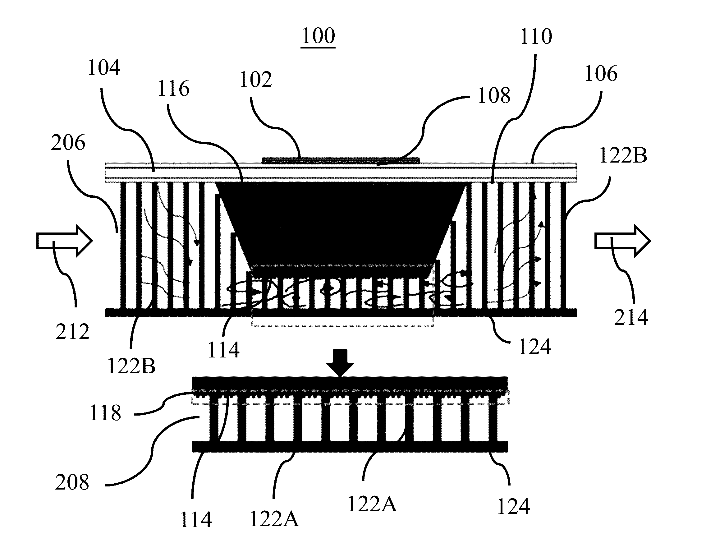
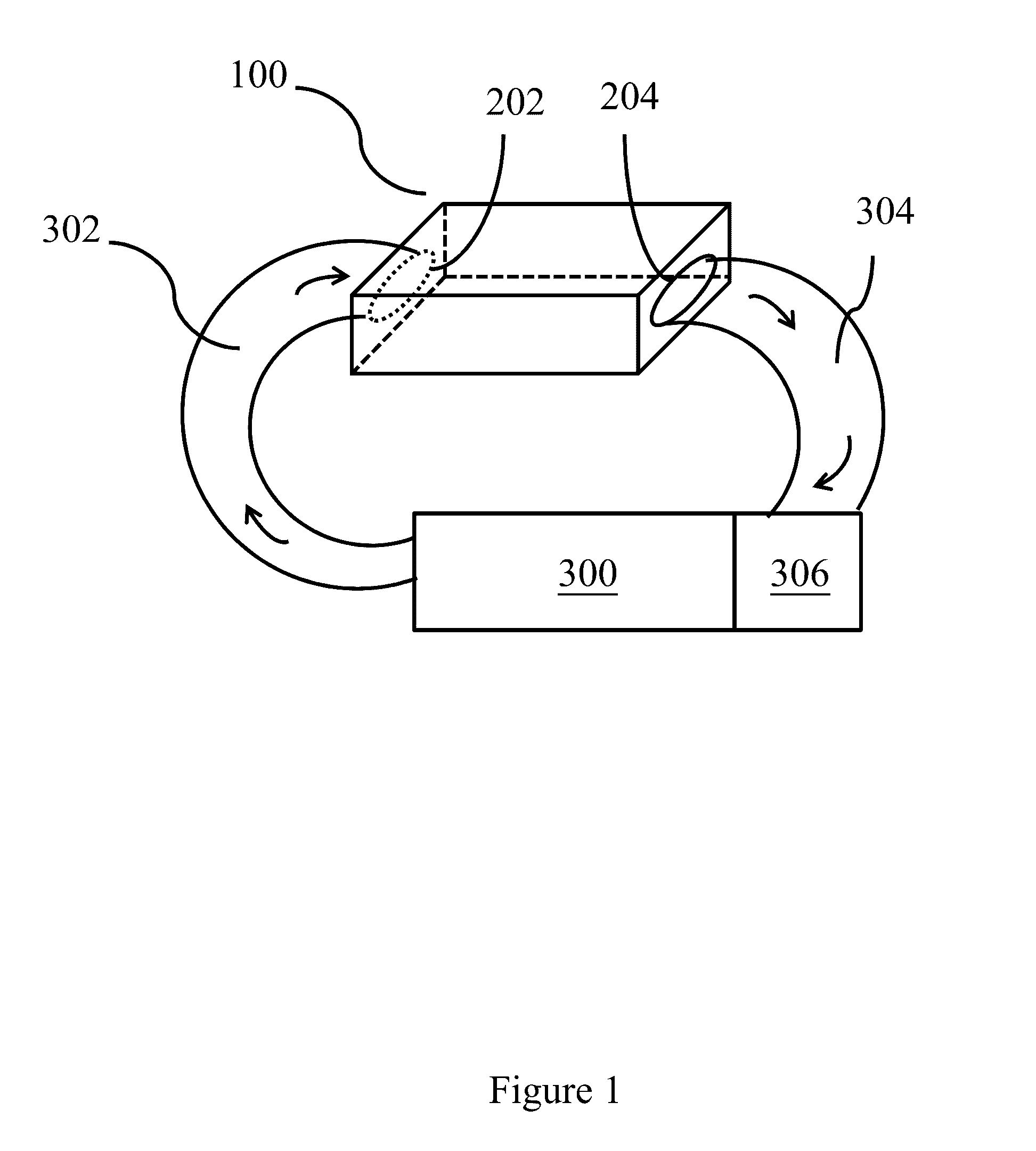
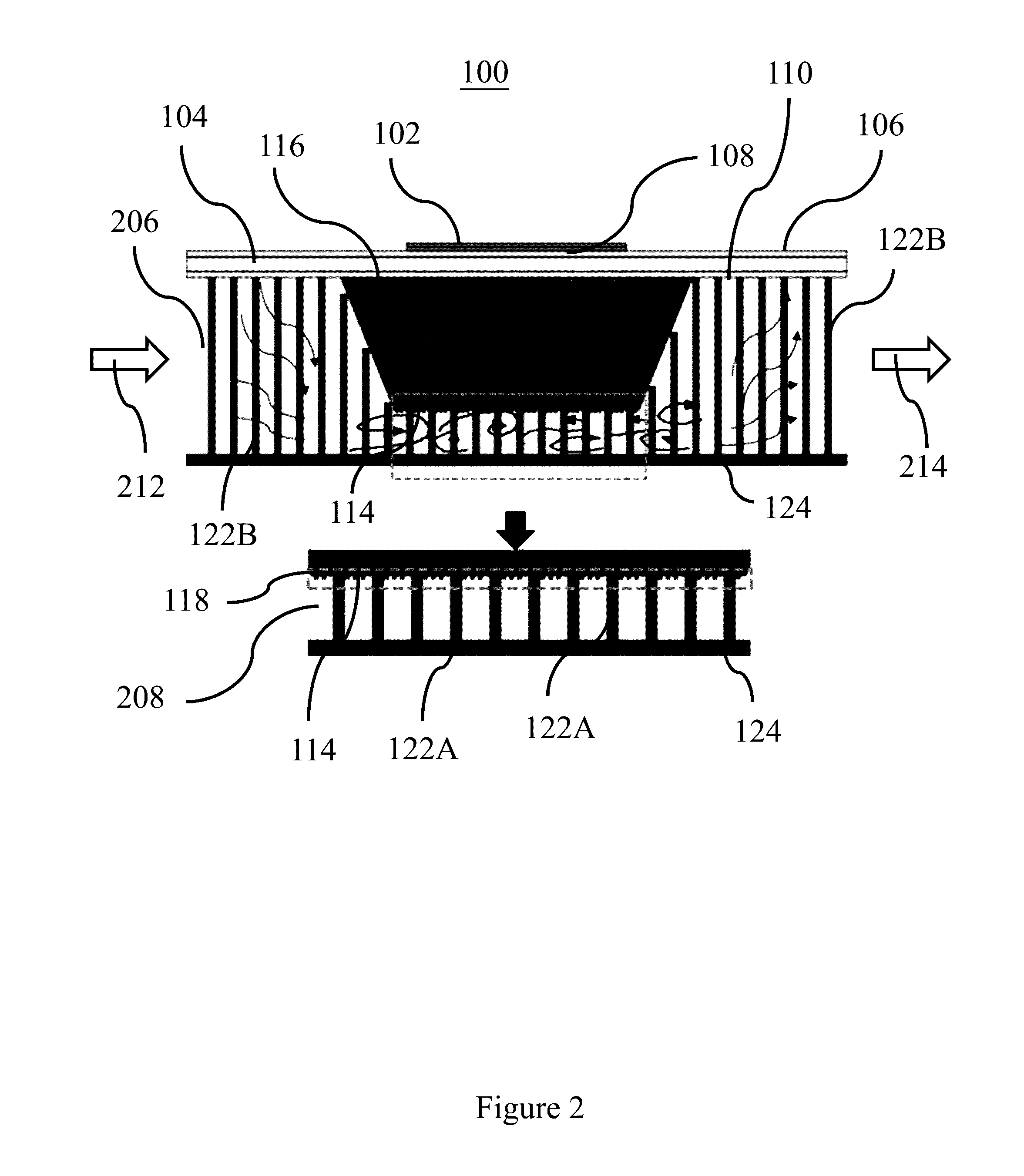
[0028]Referring to FIG. 1 and FIG. 2, an exemplary implementation of a cooling assembly 100 of this invention is shown. In this embodiment, the cooling assembly 100 is an enclosed chamber having the shape of a rectangular cube with six side plates. The cube includes: a substrate on top, a heat base on bottom, one side plate having an inlet 202, another side plate with an outlet 204 and two other side plates. The substrate is also referred to as the first plate 104 and these two terms are used interchangeably in subsequent paragraphs. Likewise, the heat base is also referred to as the second plate 124 and these two terms are also used interchangeably. A device 300 which generates pressurize liquid is coupled to the inlet 202 via a first pipe 302. The first plate 104, the second plate 124 and the two side plates form a channel 206 for liquid fluid to flow through to the...


PUM


Abstract

The present invention discloses a fluid cooling assembly which facilitates turbulent flow inside the assembly so as to achieve better heat dissipating effect. The cooling assembly comprises an enclosed chamber with an inlet and an outlet for fluid to pass through; together with a heat spreader; a plurality of micropillars and a plurality of heat dissipating fins installed inside the assembly. When fluid flows through the chamber, these elements in combination are adapted to create an enhanced turbulent flow upon the fluid so as to effectively dissipate heat from said heat spreader through the fluid.

Description

FIELD OF INVENTION[0001]This invention relates to cooling assembly, and in particular a forced fluid cooling assembly for high power electrical applications.BACKGROUND OF INVENTION[0002]High power semiconductor chips such as the insulated-gate bipolar transistor (IGBT) generate substantial amount of heat when in use. The typical operating temperature of an IGBT module is up to 200 Celsius, and it is designed to have a long service life of more than 10 years. With the advance in semiconductor fabrication technology, these devices are expected to shrink in size in the future. As such, it becomes an increasing challenging problem to design a compact cooling system that can dissipate the high density heat flux generated by these devices quickly and efficiently. As a result, liquid cooling is widely used in this area.[0003]Conventional liquid cooling solutions employ an enclosed chamber that is attached to the heat generating element(s) so that when the pressurized liquid coolant passes ...

Claims


Application Information

Patent Timeline
IPC IPC(8): H05K7/20
CPCH05K7/2039H01L23/3735H01L23/473H05K7/20927H05K7/20254H05K7/20218F28F3/022
Inventor GAO, ZIYANGLV, YATSUI, YAT KIT
Owner HONG KONG APPLIED SCI & TECH RES INST
Why Eureka
Try Eureka