Hard coating, cutting tool, and method for producing hard coating

a cutting tool and hard coating technology, applied in the direction of gear teeth, manufacturing tools, manufacturing apparatus, etc., can solve the problems of cutting tools that suffer from wear or fracturing damage of cutting edges, cutting tools that have a problem in cutting performance,

Active Publication Date: 2017-01-26
SUMITOMO ELECTRIC HARDMETAL CORP
View PDF5 Cites 27 Cited by
  • Summary
  • Abstract
  • Description
  • Claims
  • Application Information

AI Technical Summary

Benefits of technology

[0020]According to the foregoing, a hard coating capable of producing a long-life cut

Problems solved by technology

Such cutting tool often suffers from a problem of wear or fracturing damage of the cutting edge during cutting work due to exposure of the

Method used


Image

  • Hard coating, cutting tool, and method for producing hard coating
  • Hard coating, cutting tool, and method for producing hard coating
  • Hard coating, cutting tool, and method for producing hard coating

Examples


examples

[0133]The thickness of each film of a coating presented below is determined by observing a cross section of the coating by high-angle annular dark-field scanning STEM using STEM. The composition of each film of the coating presented below is obtained by three-dimensional atom probe field ion microscopic analysis. The existence of the first crystalline phases and the second crystalline phase in the hard coating described below is verified by an observation using a TEM. The minimum value of Al composition ratio x1 of the Ti1-x1Alx1N phase and the maximum value of Al composition ratio x2 of the Alx2Ti1-x2N phase presented below are calculated by EDX. A value of ((maximum value of x2)−(minimum value of x1)) presented below is calculated by obtaining the difference between the maximum value of Al composition ratio x2 of the Alx2Ti1-x2N phase and the minimum value of Al composition ratio x1 of Ti1-x1Alx1N phase. An average total thickness, presented below, of the Ti1-x1Alx1N phases and th...


PUM

PropertyMeasurementUnit
Temperatureaaaaaaaaaa

Abstract

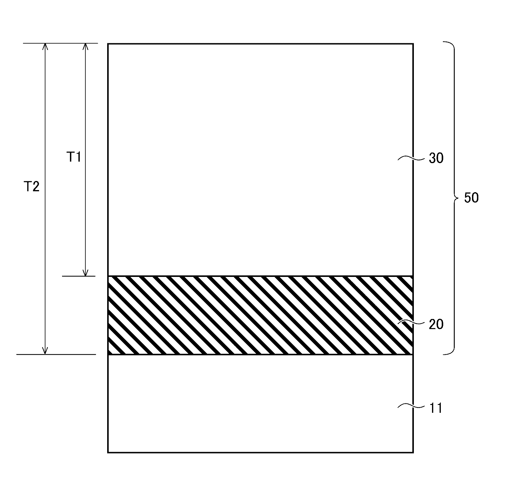
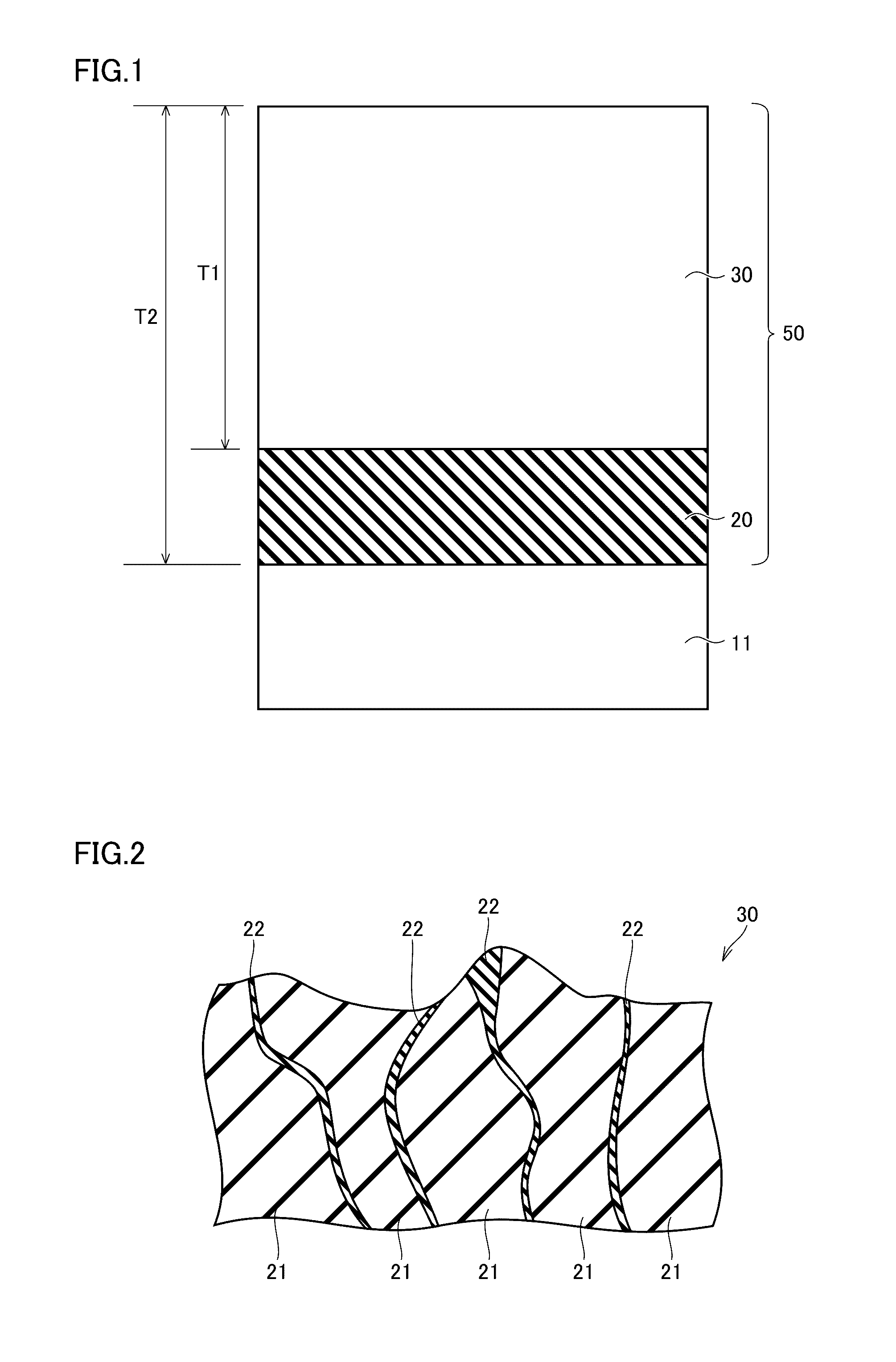
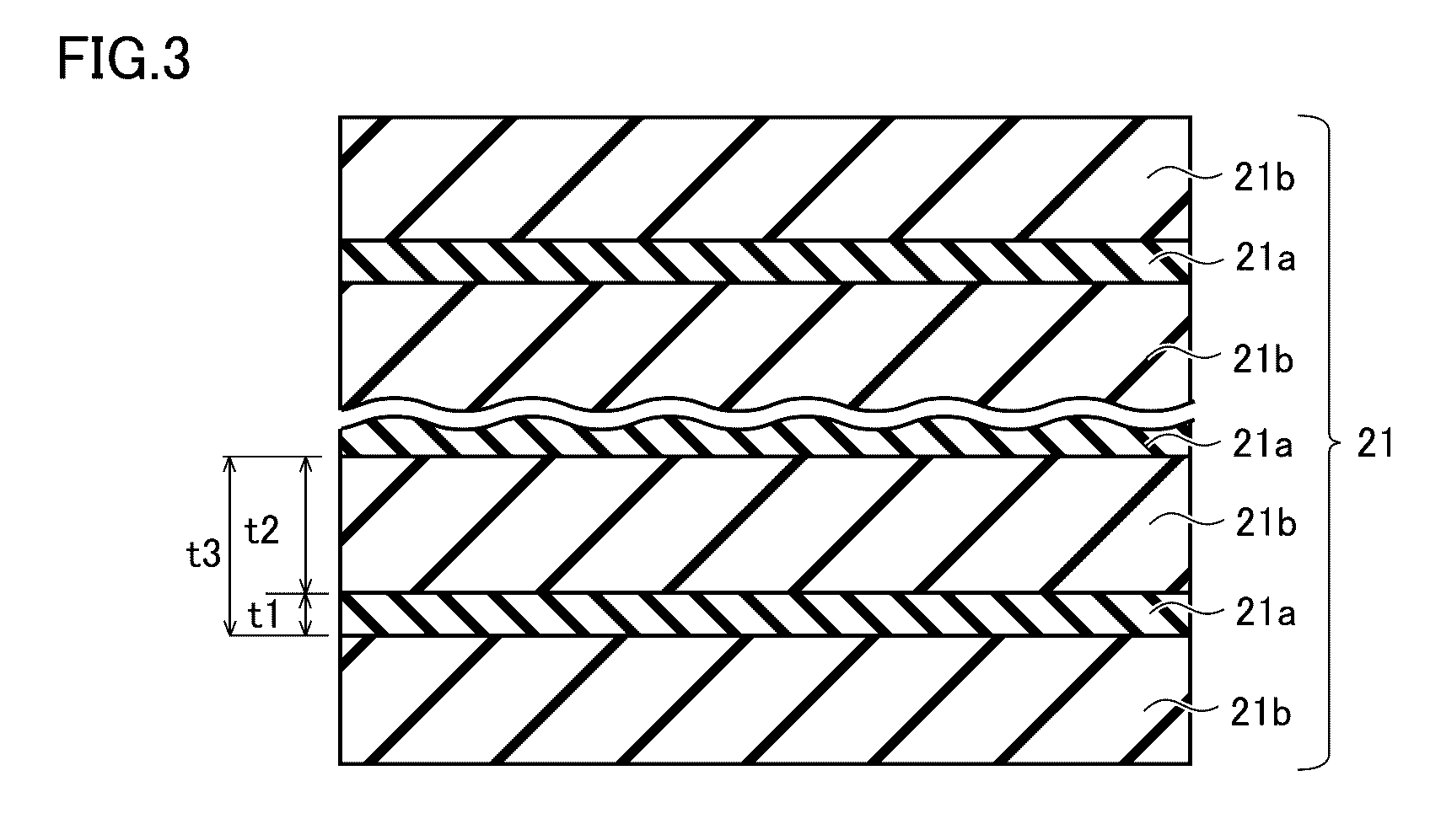
A hard coating includes two first crystalline phases, and a second crystalline phase containing AlN of a wurtzite-type crystal structure disposed therebetween. The two first crystalline phases each include, independently, a laminate structure having a Ti1-x1Alx1N phase having a sodium chloride-type crystal structure, and an Alx2Ti1-x2N phase having a sodium chloride-type crystal structure that are alternately stacked. An Al composition ratio x1 satisfies a relationship 0.5≦x1≦0.75, and an Al composition ratio x2 satisfies a relationship 0.75<x2≦0.95. The laminate structure includes a region in which an Al concentration periodically changes along a stacking direction of the Ti1-x1Alx1N phase and the Alx2Ti1-x2N phase. In this region, a difference between a maximum value of the Al composition ratio x2 and a minimum value of the Al composition ratio x1 is greater than 0.25.

Description

TECHNICAL FIELD[0001]The present invention relates to a hard coating, a cutting tool, and a method for producing a hard coating.BACKGROUND ART[0002]Cutting work on steel products, castings, and the like has conventionally been carried out using a cutting tool formed of cemented carbide. Such cutting tool often suffers from a problem of wear or fracturing damage of the cutting edge during cutting work due to exposure of the cutting edge to a tough environment, such as high temperature and high pressure. Thus, the cutting tool has a problem in cutting performance.[0003]Therefore, a coating for coating a surface of a base member, such as one formed of cemented carbide, has been under development for the purpose of improving cutting performance of cutting tools. Among others, a coating formed of a compound of titanium (Ti), aluminum (Al), and nitrogen (N) (hereinafter also referred to as “TiAlN”) can have high hardness, and can improve oxidation resistance by increasing the content rati...

Claims


Application Information

Patent Timeline
IPC IPC(8): B23B27/14C23C16/44
CPCB23B27/148B23B2228/04B23B2228/105C23C16/44B23F21/00C23C16/34C23C16/52C23C30/005C23C16/56B23B2228/10B23C2228/10B32B2307/536B32B2307/58
Inventor PASEUTH, ANONGSACKDETANI, TAKANORI
Owner SUMITOMO ELECTRIC HARDMETAL CORP
Why Eureka
Try Eureka