
Method of controlling electric motors, corresponding system, electric motor and computer program product

Active Publication Date: 2017-01-26
STMICROELECTRONICS SRL
View PDF4 Cites 5 Cited by
  • Summary
  • Abstract
  • Description
  • Claims
  • Application Information

AI Technical Summary

Benefits of technology

The patent text describes a way to correct errors caused by using a modulated clock for motor control applications. This method can reduce the need for other techniques such as filtering and shielding, which can save time and money.

Problems solved by technology

High speed clocking signals used to control these integrated circuits (ICs) may, however, generate EMI and, as a consequence, present more challenges for designers of consumer, enterprise, communications and embedded equipment.

Method used


Image

  • Method of controlling electric motors, corresponding system, electric motor and computer program product
  • Method of controlling electric motors, corresponding system, electric motor and computer program product
  • Method of controlling electric motors, corresponding system, electric motor and computer program product

Examples


Embodiment Construction

[0017]In the ensuing description one or more specific details are illustrated, aimed at providing an in-depth understanding of examples of embodiments. The embodiments may be obtained without one or more of the specific details, or with other methods, components, materials, etc. In other cases, known structures, materials, or operations are not illustrated or described in detail so that certain aspects of embodiments will not be obscured.

[0018]Reference to “an embodiment” or “one embodiment” in the framework of the present description is intended to indicate that a particular configuration, structure, or characteristic described in relation to the embodiment is comprised in at least one embodiment. Hence, phrases such as “in an embodiment” or “in one embodiment” that may be present in one or more points of the present description do not necessarily refer to one and the same embodiment. Moreover, particular conformations, structures, or characteristics may be combined in any adequate...


PUM


Abstract

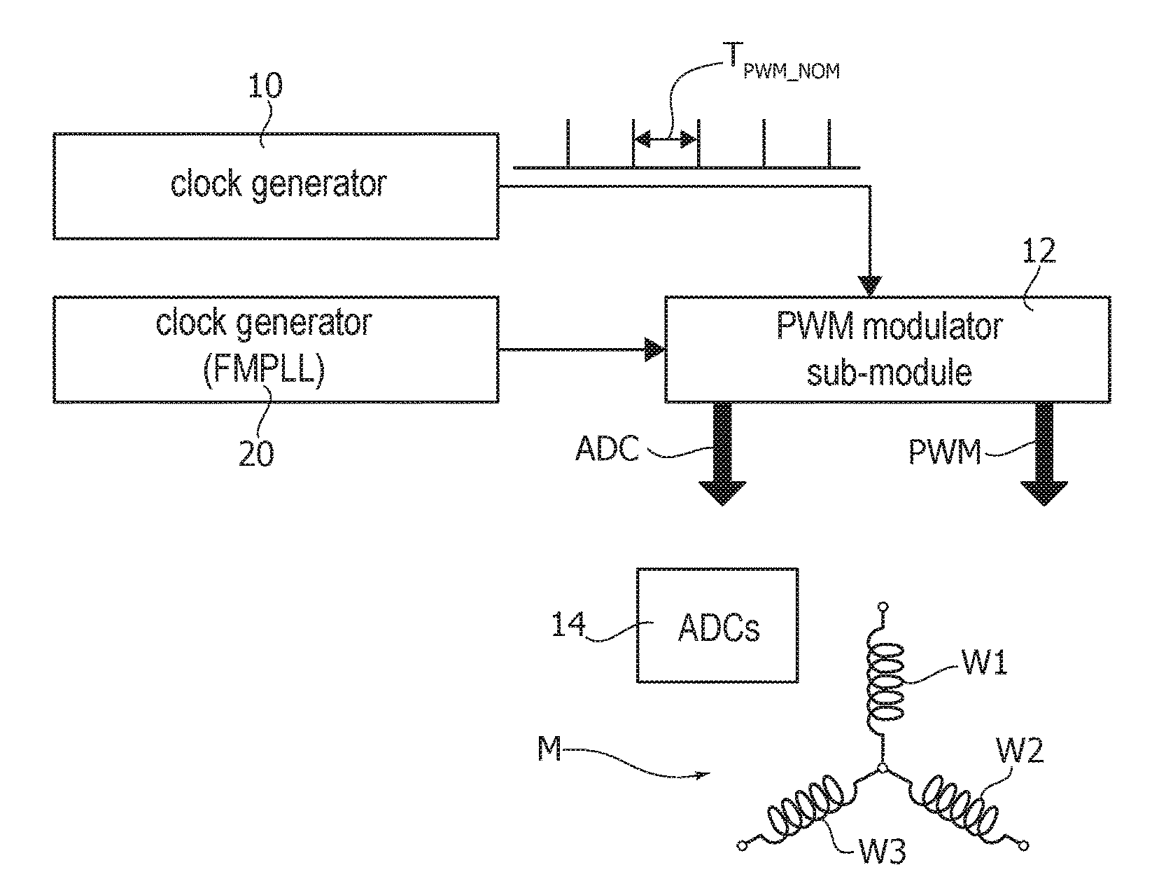
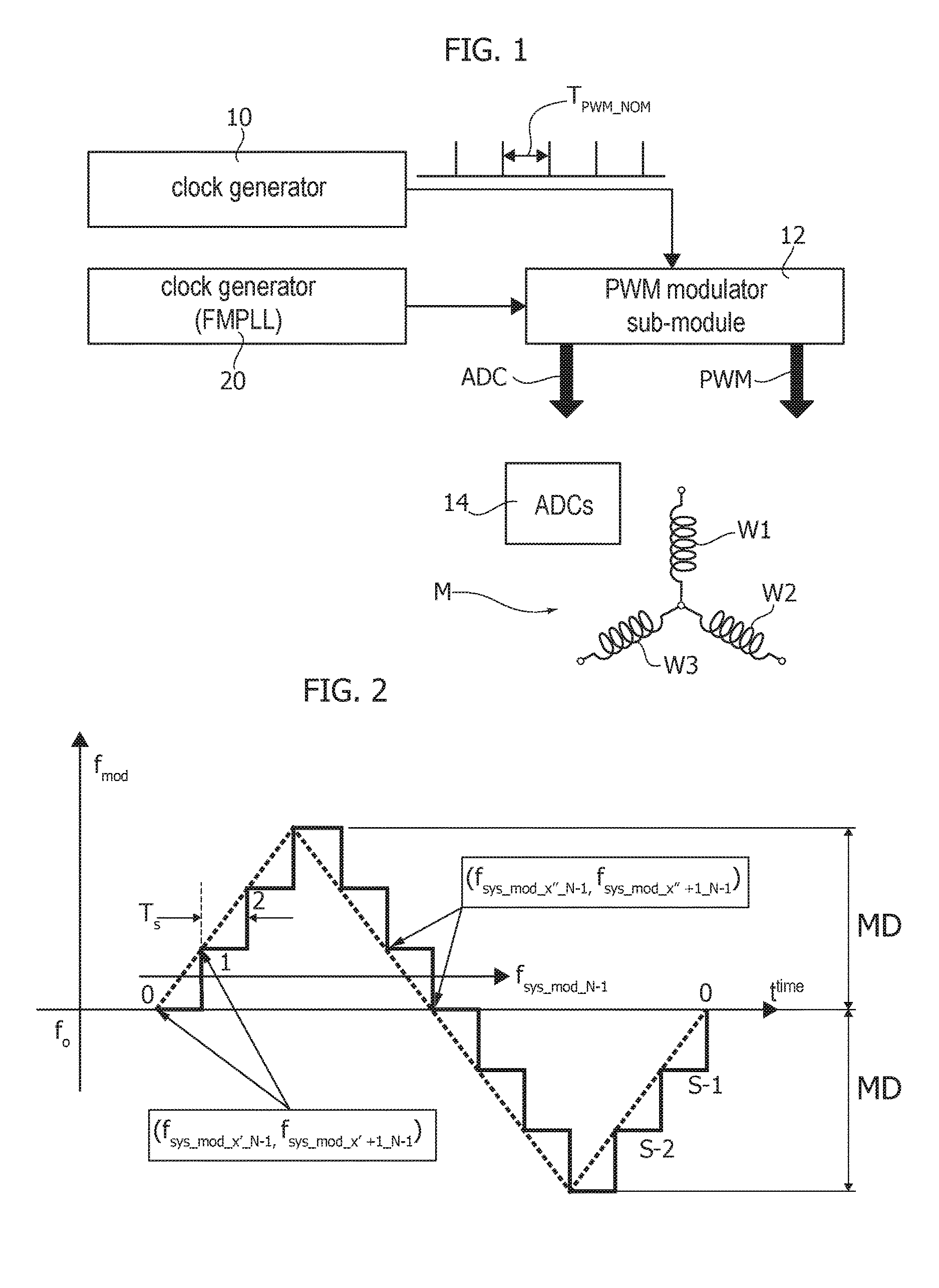
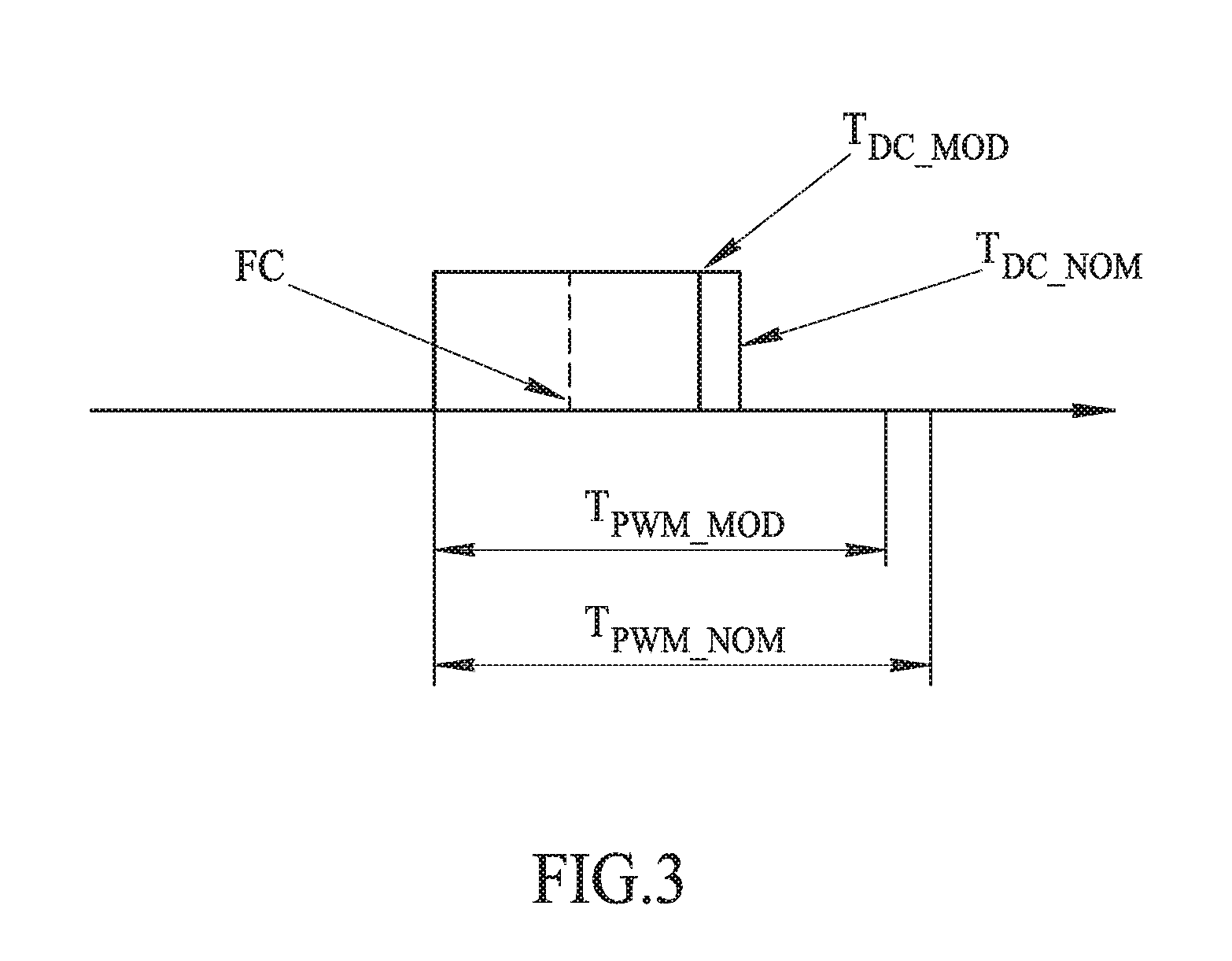
An electric motor is controlled by means of pulse-width modulated control signal having edge transitions occurring at certain transition count values of the pulses of a clock signal which is frequency-modulated with a step-wise frequency modulation (e.g., SSCG or Spread Spectrum Clock Generation). A frequency unmodulated clock signal is provided having a fixed period indicative of the period of the pulse-width modulated control signals. The transition count values are set as a function of a predicted count value and / or a predicted frequency value for the frequency-modulated clock signal. Prediction occurs as a function of the frequency unmodulated clock signal, so that the transition count values are compensated against the step-wise (e.g., SSCG) frequency modulation.

Description

BACKGROUND[0001]Technical Field[0002]The description relates generally to controlling electric motors and one or more embodiments relate to electric motor control applications with a triangle wave modulated system clock.[0003]Description of the Related Art[0004]Electromagnetic interference (EMI), once the exclusive concern of equipment designers working with high speed signals, is no longer limited to a narrow class of high-end applications. Continued innovation in semiconductor technology has resulted in the ready availability of cost effective, high performance System-on-Chip (SoC) devices, MicroController Units (MCUs), processors, Digital Signal Processors (DSPs), Application Specific Integrated Circuits (ASICs), Field Programmable Gate Arrays (FPGAs) and Analog / Digital Converters (ADCs).[0005]High speed clocking signals used to control these integrated circuits (ICs) may, however, generate EMI and, as a consequence, present more challenges for designers of consumer, enterprise, ...

Claims


Application Information

Patent Timeline
IPC IPC(8): H02K11/02H03K4/06H02P31/00
CPCH02K11/02H03K4/06H02P31/00H02P27/08H02M7/5395
Inventor D'ANGELO, GIUSEPPEBISOGNO, MICHELECLEMENTE, VIRGINIA
Owner STMICROELECTRONICS SRL
Learn More