
A device and method for cancer detection, diagnosis and treatment guidance using active thermal imaging

a technology of active thermal imaging and cancer detection, applied in the field of cancer detection and diagnosis, can solve the problems of low survival rate of lung cancer, untreatable, and large tumor size, and achieve the effect of reducing the risk of cancer, reducing and improving the survival rate of cancer

Inactive Publication Date: 2017-02-02
H T BIOIMAGING LTD
View PDF2 Cites 16 Cited by
  • Summary
  • Abstract
  • Description
  • Claims
  • Application Information

AI Technical Summary

Benefits of technology

The patent describes a system that can collect data on tissue temperature and apply heat to that tissue to calculate a heat transfer index in real-time. This index indicates the severity of a medical condition in that tissue. The system uses a normalizing step to adjust the data to a standard scale, with higher values indicating higher severity of the medical condition. The technical effect of this system is the ability to accurately measure the heat transfer in tissue and provide a real-time assessment of the severity of a medical condition.

Problems solved by technology

This extremely low survival rate of lung cancer is not due to lung tumors being more aggressive than other malignant tumors types, but in fact is due to the lack of early detection.
Therefore breathing difficulties and coughing which usually leads to the diagnosis of the cancer means the tumor is large enough to be noticed and is probably untreatable.
At this stage the cancer is progressive and usually metastatic and a targeted healing therapy cannot be considered, resulting in a five year survival rate which is very low.
These false positives lead to unnecessary biopsies and unnecessary treatment for healthy person.
In addition, oncologists treating the cancer have great difficulty in monitoring the treatment progress, and even cataloging the different stages of the disease.
Treatment methods would then be changed, losing valuable time.
In other cases cancer cells would successfully be destroyed, and turn into necrotic cells, however, traditional scans would not differentiate them from cancer cells.
Moreover, Pap test is expensive and requires 14-30 days of waiting for the cytology testing.
However, the use of passively occurring radiation only renders '902 to be incompetent in detecting minor differences in cell structure, which are already found in the precancerous stage.
However, in the above documents, to Herman, the skin surface is cooled by application of cold fluid to a region of the surface, so that Herman can only identify lesions at or very near the surface.

Method used


Image

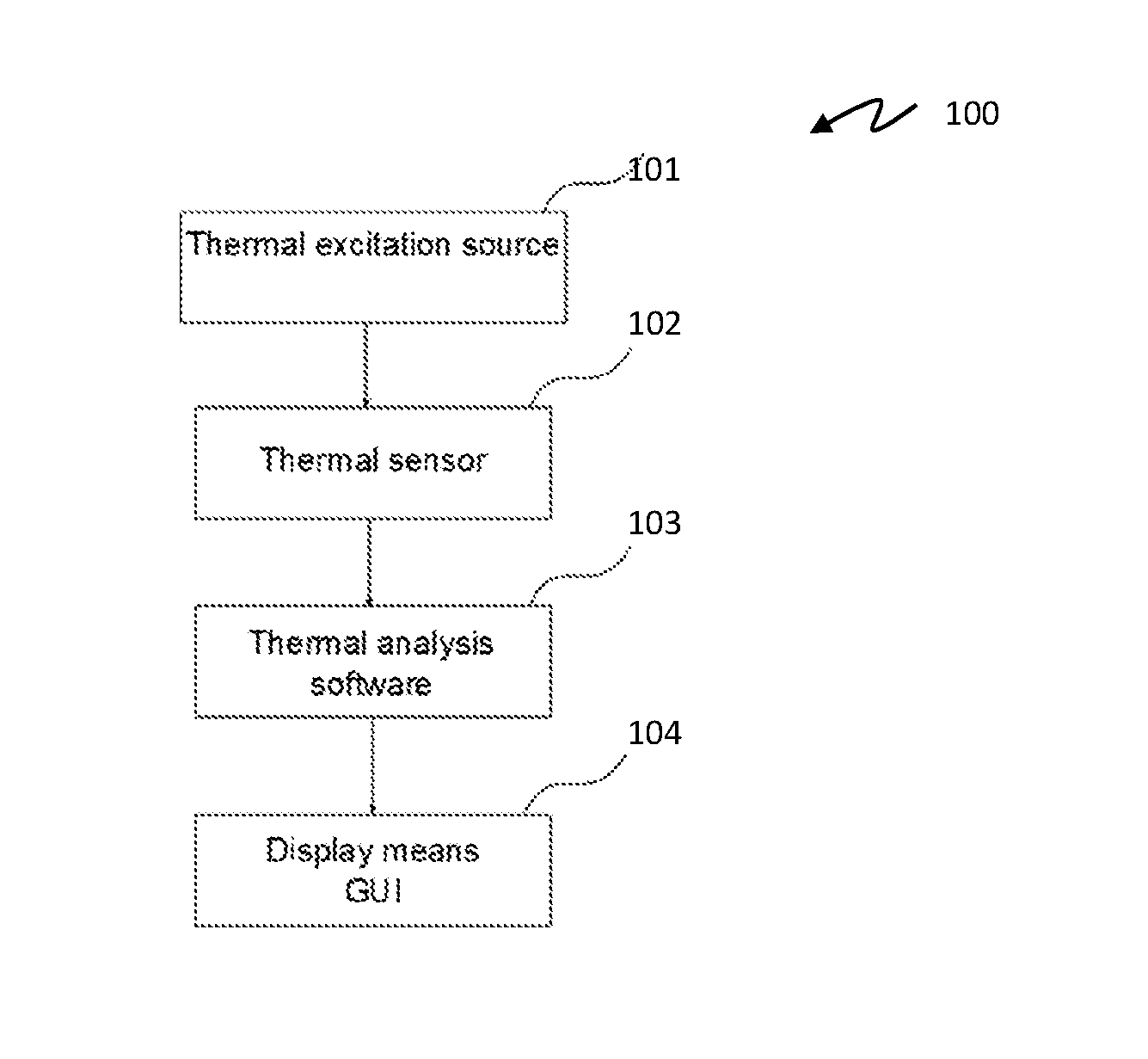
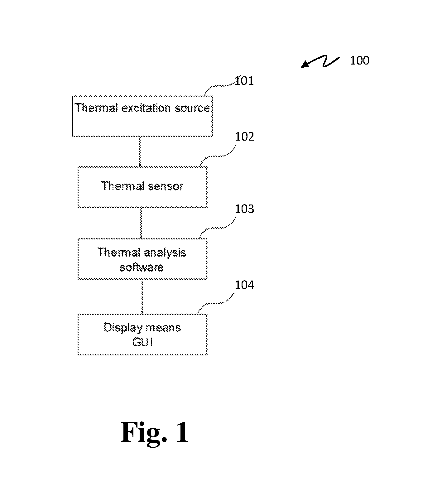
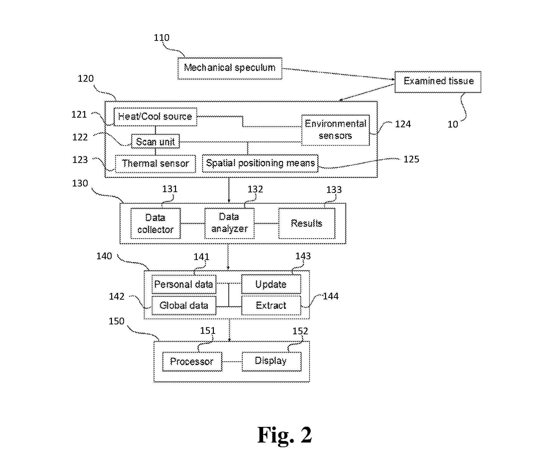
  • A device and method for cancer detection, diagnosis and treatment guidance using active thermal imaging
  • A device and method for cancer detection, diagnosis and treatment guidance using active thermal imaging
  • A device and method for cancer detection, diagnosis and treatment guidance using active thermal imaging

Examples


example 1

[0307]The experimental set up used to evaluate the invention is comprised of two stages. The second stage is designed to achieve greater accuracy and elaboration of the results obtained in the first stage, in addition to handling experimental issues and difficulties arising in the first experimental stage. The second stage was conducted in view of the results obtained in the first. Experimental design goes as follows:

[0308]Image capturing of all cell cultures; Laboratory conditions take into account: (a) Neutralizing disturbances; (b) Constant temperature, registration of any alterations. (c) Registration of humidity values.

[0309]Camera set up: Control set up—heating; Control set up—cooling; Conduct experiments using heating; Conduct experiments using cooling.

example 2

[0310]The system of the present invention can be configured as a ‘decision support’ system, informing a user such as a clinician as to whether a positive CT result is a cancer (true positive) and requires further investigation, or whether the positive CT result is a false positive.

[0311]With the system of the present invention, the results are immediate, do not involve radiation risks and are independent of an expert's eye. The test is computerized and automatic, with no need for a long, expensive analyzing stage.

[0312]As disclosed above, the technology is based upon analysis of the temperature decay profile and measurement of heat diffusion in the lung. It is well known that the density of cancerous cells is higher than that of normal cells, their shape is different and their nuclei are enlarged. These differences cause a fundamental change in the thermal properties of the cells. The planned operating principle—short heating followed by tracking diffusion of heat into the tissue an...

example 3

[0323]A simulation of a method of generating a thermal diffusion image is demonstrated on a horizontal slice of a human thorax (chest), which includes the lungs and the heart. FIG. 10 shows a CT image of a normal human thorax (1000), showing the heart (1010), spine (1020), lungs (1030), and the bones (1040), muscles (1050) and fat (1060). These have been overlaid with lines indicating the simplified shapes for the organs which will be used in the simulation. The spine (1020) is simulated by a triangle, the heart (1010) by an oval, with the inner and outer limits of the bone (1040), muscle (1050) and fat (1060) being indicated by concentric ovals. The lungs (1030) occupy the space between the oval of the heart (1010) and the triangle of the spine (1020) as inner limits to the lungs and the inner perimeter of the bone (1040) as the outer limits to the bone.

[0324]FIG. 11 shows the simplified shapes of the organs (1100), without the CT scan. In FIG. 11, the heart (1010) is indicated by ...


PUM


Abstract

The present invention discloses means and methods for detecting irregularities in the cells throughout a healthy tissue. The method generally relates to cancer detection, diagnosis and treatment, and more specifically pertains to detection, diagnosis and treatment guidance of cancerous or precancerous conditions through the use of thermal imaging technology and analysis.

Description

CROSS-REFERENCE TO RELATED APPLICATIONS[0001]This application is a U.S. National Phase filing under 35 U.S.C. 371 of International (PCT) Patent Application No. PCT / IL2015 / 050392, filed 13 Apr. 2015, which claims priority from U.S. Provisional Patent Application No. 62 / 110,615, filed 2 Feb. 2015, and from U.S. Provisional Patent Application No. 61 / 978,901, filed 13 Apr. 2014, all of which are incorporated by reference in their entirety.FIELD OF THE INVENTION[0002]The present invention relates to cancer detection and diagnosis, and more specifically the present invention relates to cancer detection and diagnosis through the use of thermal imaging technology.BACKGROUND OF THE INVENTION[0003]Tumor cells are distinct from their surrounding normal tissue by several properties, one of which is a thermo-physical property referred to as thermal diffusivity, which is expected to be different in cancerous cells compared to healthy cells. Thermal diffusivity is the combined property of density,...

Claims


Application Information

Patent Timeline
Patent Type & Authority Applications(United States)
IPC IPC(8): A61B5/01A61B5/00A61B5/08
CPCA61B5/01A61B5/08A61B2560/0252A61B5/015A61B5/742A61F7/00G16H50/30G16H50/70G16H50/20A61B5/0077A61B2562/0271G01J5/00G06T7/0012G06T2207/10048G06T2207/30096G06T2207/30104G01J5/48
Inventor TOLEDANO, SHANIROSENBACH, YOAVTSHUVA, MOSHEGAT, SHARON
Owner H T BIOIMAGING LTD
Learn More