Quantum rod layer, method of fabricating the same and display device including the same

a technology of quantum rods and fabrication methods, applied in the field of quantum rods, can solve the problems that the lcd device b>10/b> may become vulnerable to environmental regulation, and achieve the effects of reducing fabrication costs, improving the degree of alignment of quantum rods, and improving polarization properties

Active Publication Date: 2017-02-02
LG DISPLAY CO LTD
View PDF7 Cites 8 Cited by
  • Summary
  • Abstract
  • Description
  • Claims
  • Application Information

AI Technical Summary

Benefits of technology

[0022]An object of the invention is to provide a quantum rod layer where a polarization property is improved and a fabrication cost is reduced by improving a degree of alignment of a quantum rod using a photo-induced polymer, a method of fabricating the quantum rod layer and a display device including the quantum rod layer.
[0023]Another object of the invention is to provide a display device including a quantum rod layer where a fabrication cost is reduced, a brightness increases and a power consumption is reduced by using the quantum rod layer as a polarizing plate due to improvement of a degree of alignment of a quantum rod and a polarization property of the quantum rod layer.
[0024]Another object of the invention is to provide a display device including a quantum rod layer where a fabrication cost is reduced, a brightness increases and a power consumption is reduced by using the quantum rod layer as a polarizing plate and an alignment layer due to improvement of a degree of alignment of a quantum rod and a polarization property of the quantum rod layer.

Problems solved by technology

In addition, since an amount of a material for the QR, e.g., a material of a cadmium (Cd) family increases, the LCD device 10 may become vulnerable to an environmental regulation.

Method used


Image

  • Quantum rod layer, method of fabricating the same and display device including the same
  • Quantum rod layer, method of fabricating the same and display device including the same
  • Quantum rod layer, method of fabricating the same and display device including the same

Examples


first embodiment

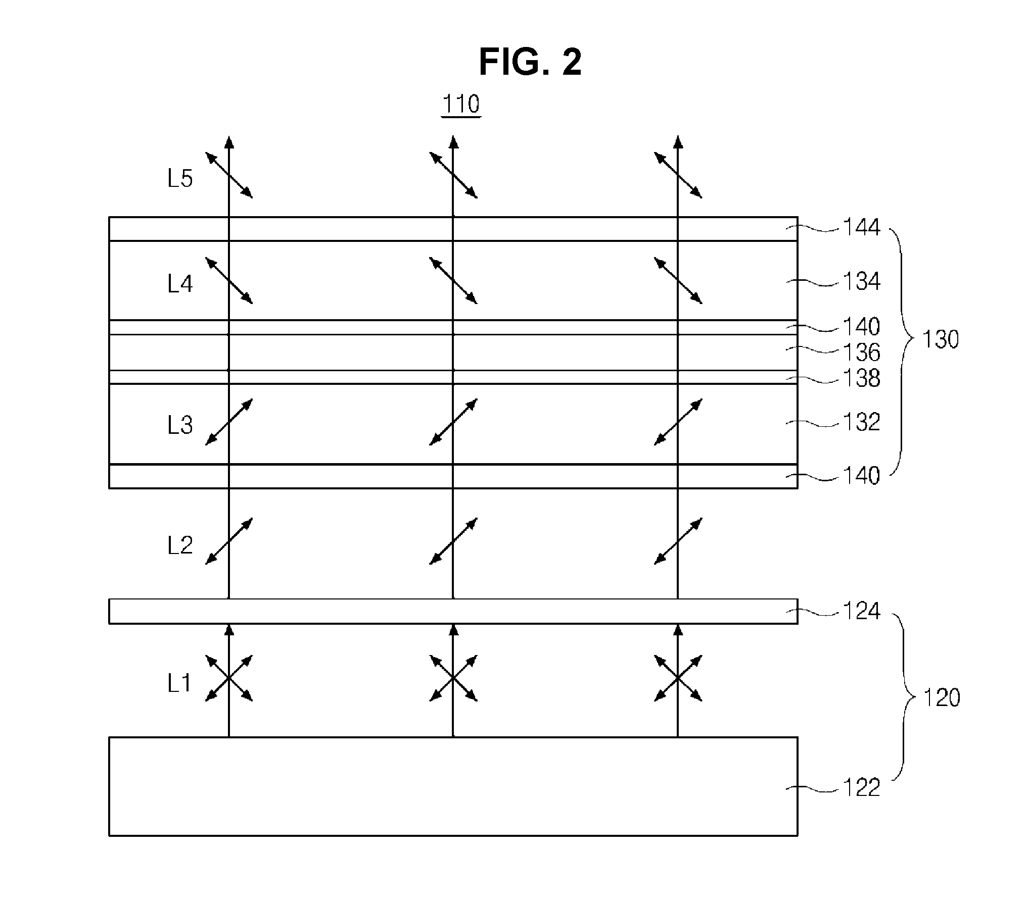
[0037]FIG. 2 is a liquid crystal display device including a quantum rod layer according to the present invention. All the components of the liquid crystal display device according to all the embodiments of the present invention are operatively coupled and configured.

[0038]In FIG. 2, a liquid crystal display (LCD) device 110 according to a first embodiment of the present invention includes a backlight unit 120 supplying a light and a liquid crystal panel 130 displaying an image using the light of the backlight unit 120.

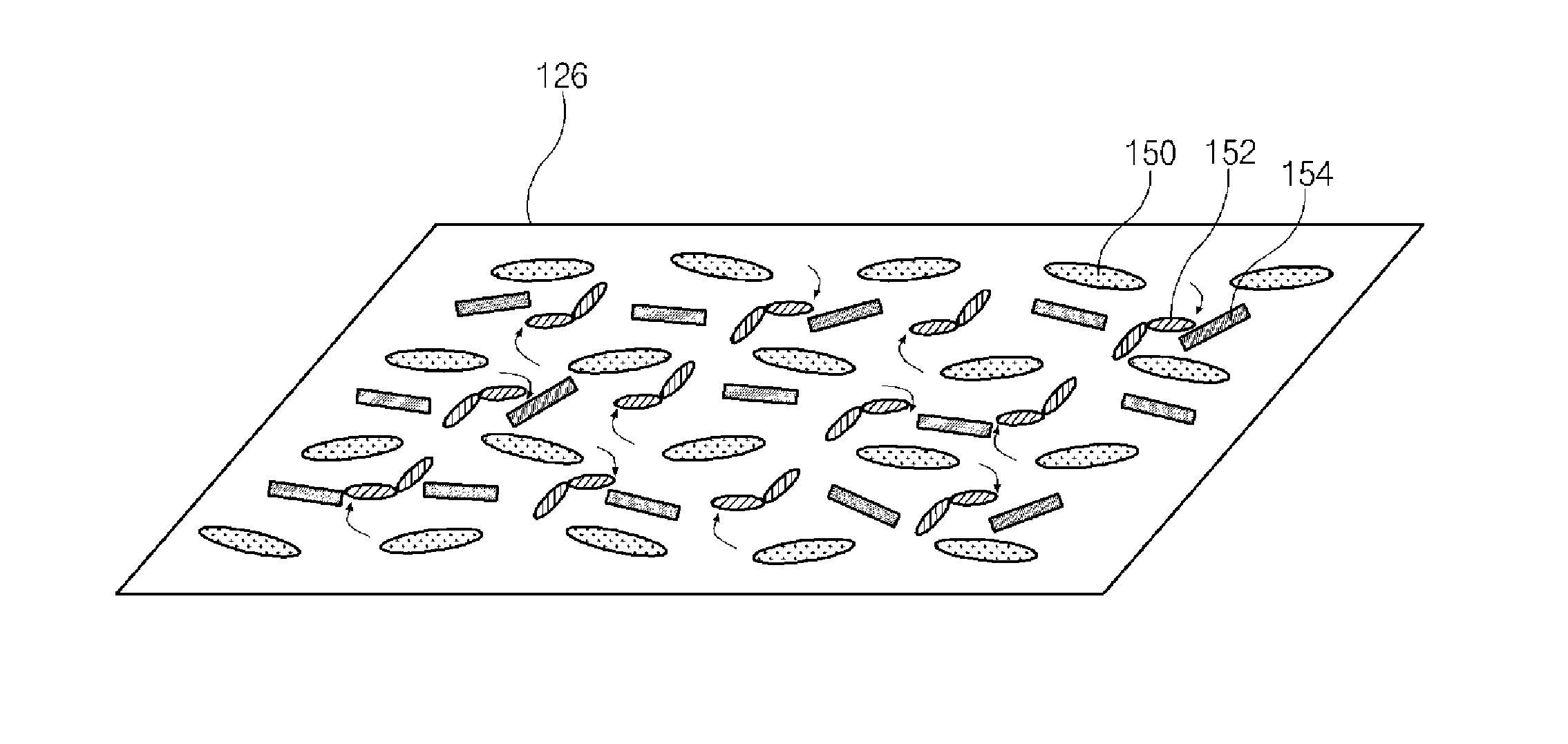
[0039]The backlight unit 120 includes a light source part 122 emitting a light and a quantum rod (QR) layer 124 emitting a light of a polarized state whose peak wavelength property is improved using the light of the light source part 122.

[0040]The light source part 122 may emit a blue colored light. For example, the light source part 122 of an edge type may include a light source such as a light emitting diode (LED) emitting a blue colored light and a light guide plate...

second embodiment

[0102]In FIG. 4, a liquid crystal display (LCD) device 210 according to the present invention includes a backlight unit 220 supplying a light and a liquid crystal panel 230 displaying an image using the light of the backlight unit 220.

[0103]The backlight unit 220 includes a light source part (not shown) emitting a light and the light source part may emit a blue colored light.

[0104]For example, the light source part of an edge type may include a light source such as a light emitting diode (LED) emitting a blue colored light and a light guide plate disposed at a side of the light source and transmitting the light of the light source by changing a path. In addition, the light source part of a direct type may include a light source such as an LED emitting a blue colored light and an optical sheet over the light source and transmitting the light of the light source uniformly.

[0105]The liquid crystal panel 230 includes first and second substrates 232 and 234 facing and spaced apart from e...

third embodiment

[0123]In FIG. 5, a liquid crystal display (LCD) device 310 according to the present invention includes a backlight unit 320 supplying a light and a liquid crystal panel 330 displaying an image using the light of the backlight unit 320.

[0124]The backlight unit 320 includes a light source part (not shown) emitting a light and the light source part may emit a blue colored light.

[0125]For example, the light source part of an edge type may include a light source such as a light emitting diode (LED) emitting a blue colored light and a light guide plate disposed at a side of the light source and transmitting the light of the light source by changing a path. In addition, the light source part of a direct type may include a light source such as an LED emitting a blue colored light and an optical sheet over the light source and transmitting the light of the light source uniformly.

[0126]The liquid crystal panel 330 includes first and second substrates 332 and 334 facing and spaced apart from e...


PUM

PropertyMeasurementUnit
wavelengthaaaaaaaaaa
temperatureaaaaaaaaaa

Abstract

An example of the present invention provides a quantum rod layer including: a photo-induced polymer including a base polymer aligned along a first direction and a photo-reactive group combined to the base polymer; and a quantum rod aligned along the first direction.

Description

CROSS-REFERENCE TO RELATED APPLICATION[0001]This application claims priority to and the benefit of Korean Patent Application No. 10-2015-0107152 filed in Korea on Jul. 29, 2015 and Korean Patent Application No. 10-2015-0172338 filed in Korea on Dec. 4, 2015, which are hereby incorporated by reference.BACKGROUND OF THE INVENTION[0002]Field of the Invention[0003]Embodiments of the invention relate to a quantum rod layer, and more particularly, to a quantum rod layer having an improved polarization property, a method of fabricating the quantum rod layer and a display device including the quantum rod layer.[0004]Discussion of the Related Art[0005]Recently, as the society has entered in earnest upon an information age, a field of display devices that represent all sorts of electrical signals as visual images has developed rapidly. Flat panel display devices, such as a liquid crystal display (LCD) device, a plasma display panel (PDP) device, a field emission display (FED) device and an or...

Claims


Application Information

Patent Timeline
Patent Type & Authority Applications(United States)
IPC IPC(8): G02F1/1335G02F1/1337
CPCG02F1/133617G02F1/133528G02F2001/133614G02F1/13362G02F1/1337G02F1/133531C09K2323/02C09K2323/03G02F1/133788G02F1/3532G02F2202/36G02F1/133614B32B2457/202G02B5/3025H01L31/035227
Inventor PARK, SEUNG-RYULLPARK, HYUN-JINAHN, HAN-JIN
Owner LG DISPLAY CO LTD
Why Eureka
Try Eureka