Gas turbine combustor and gas turbine provided with same

Active Publication Date: 2017-02-16
MITSUBISHI POWER LTD
View PDF1 Cites 0 Cited by
  • Summary
  • Abstract
  • Description
  • Claims
  • Application Information

AI Technical Summary

Benefits of technology

The gas turbine combustor described in this patent increases the heat transfer coefficient by using the collision and separation of the cooling medium at the passage transition groove portion. This allows for cooling to be achieved with a low cooling medium flow rate or pressure loss, improving cycle performance. The gas turbine includes this efficient combustor, which increases the combustion temperature and the turbine inlet temperature.

Problems solved by technology

In gas turbine combustors, combustion gas flowing through the inside thereof can cause the wall temperature to exceed the tolerable temperature of its material.

Method used


Image

  • Gas turbine combustor and gas turbine provided with same
  • Gas turbine combustor and gas turbine provided with same
  • Gas turbine combustor and gas turbine provided with same

Examples


embodiments

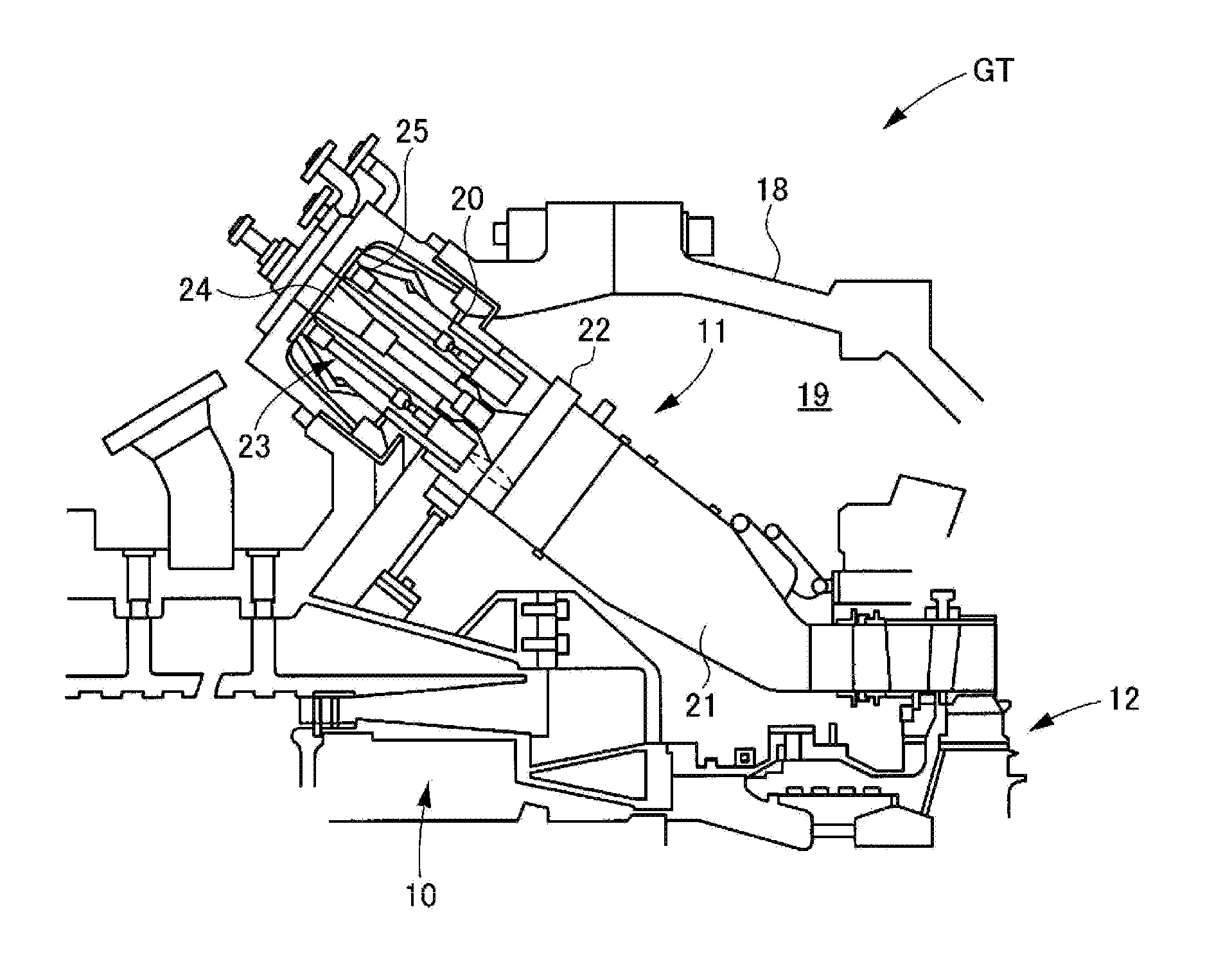
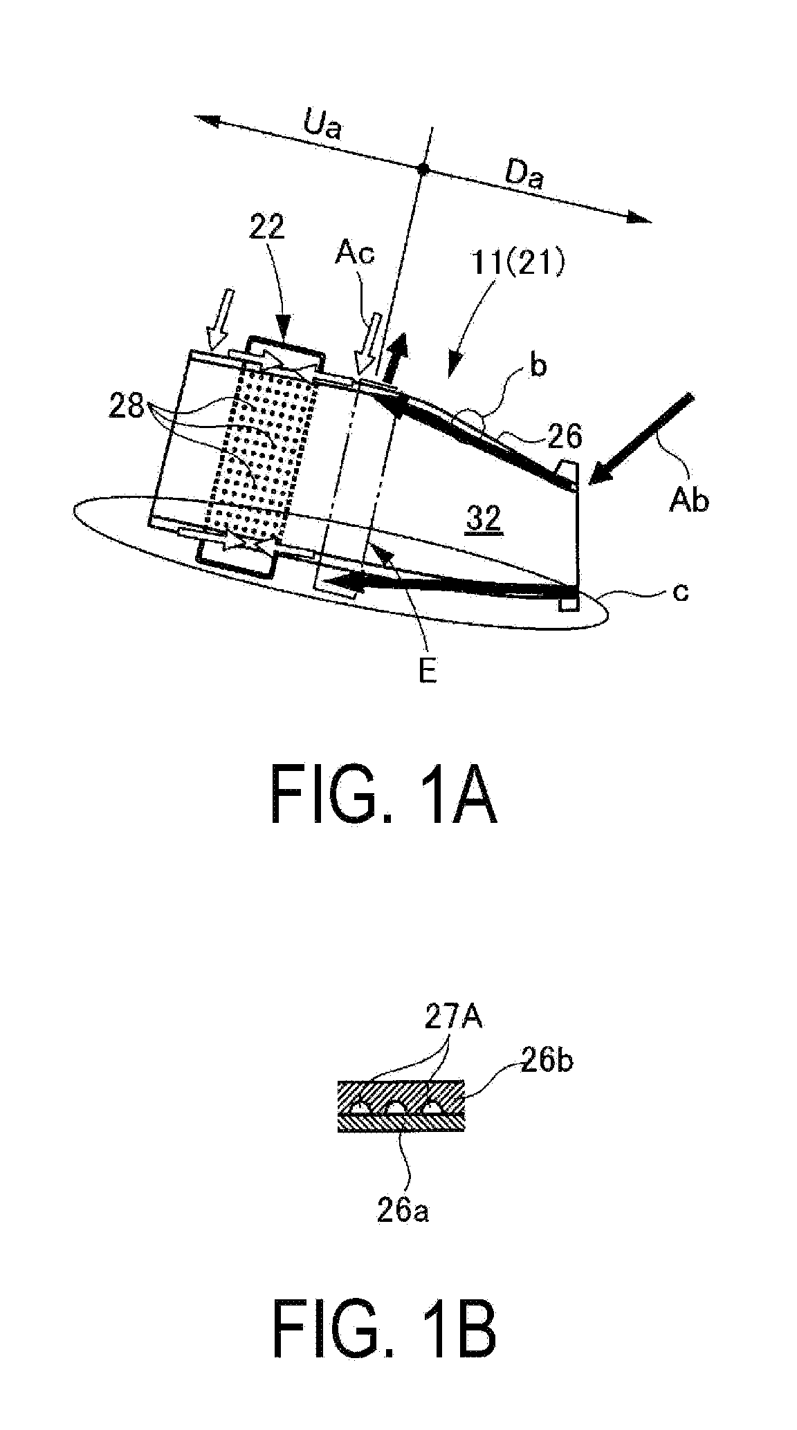
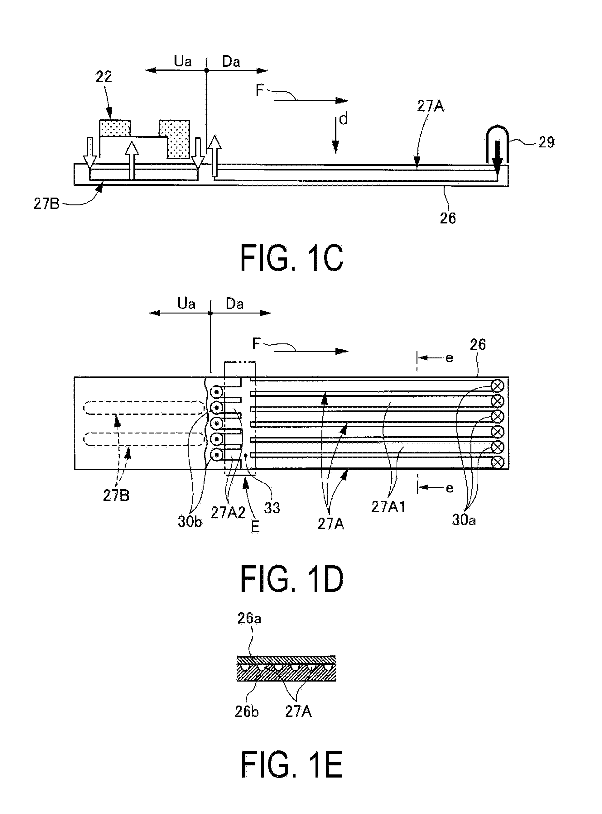
[0051]FIGS. 1A to 1E are explanatory diagrams of a closed air cooling cycle cooling structure of a combustor, which is an embodiment of the present invention. FIGS. 2A to 2C are explanatory diagrams of the structure and operational effects of a passage transition groove portion. FIG. 3A and FIG. 3B are cross-sectional views of cooling air passages through which bled pressurized air flows. FIG. 4 is an explanatory diagram illustrating an example of the structure of a gas turbine provided with the combustor including the closed air cooling cycle cooling structure. FIG. 5 is an explanatory diagram illustrating the structure of the combustor including the closed air cooling cycle cooling structure.

[0052]As illustrated in FIG. 4, a gas turbine GT includes a compressor 10, a combustor 11, and a turbine 12. The turbine 12 is coupled to a generator Ge.

[0053]The compressor 10 compresses air In taken in from the atmosphere. The main flow of this compressed air is supplied to the combustor 11 ...


PUM


Abstract

A gas turbine combustor comprising a plurality of cooling air passages (27A) through which bled pressurized air flows from downstream of a combustion gas flow toward upstream, the plurality of cooling air passages (27A) being disposed in a wall portion (26) side by side and aligned in a flow direction of a combustion gas; wherein the plurality of cooling air passages (27A) are divided via a passage transition groove portion (33) into upstream cooling air passages (27A1) disposed closer to bled pressurized air inlet holes (30a) and downstream cooling air passages (27A2) disposed closer to bled pressurized air outlet holes (30b), and center lines (C1) of the upstream cooling air passages are non-collinear with center lines (C2) of the downstream cooling air passages.

Description

TECHNICAL FIELD[0001]The present invention relates to a gas turbine combustor and a gas turbine provided with the gas turbine combustor.BACKGROUND ART[0002]In gas turbine combustors, combustion gas flowing through the inside thereof can cause the wall temperature to exceed the tolerable temperature of its material. To prevent this, a cooling structure is provided. Many examples of such a cooling structure of a gas turbine combustor are known that employ a method of cooling by passing a cooling medium, such as compressed air or steam, to the wall portion.[0003]One such example is the technology described in Patent Document 1. The technology described is a closed air cooling cycle cooling structure wherein, as illustrated in FIGS. 6A to 6E, compressed air supplied from a compressor (not illustrated) is bled from the side upstream of a combustor 100 and this pressurized bled pressurized air Ab is used to cool a wall portion (wall) 101. Thereafter, the bled pressurized air Ab is recover...

Claims


Application Information

Patent Timeline
IPC IPC(8): F02C7/18F02C3/14
CPCF02C3/14F02C7/18F23R3/42F23R3/005F23R3/06Y02T50/60F05D2260/232F05D2220/32F02C7/08F02C7/24
Inventor YAMAGUCHI, YOSHIAKIMIZUKAMI, SATOSHIHIRATA, TOMOYUKIMASADA, JUNICHIROKONISHI, TETSUTAKATA, KAZUMASAYAMAZAKI, HIROYUKISUZUKI, TAKUYAISHIKAWA, SHINYA
Owner MITSUBISHI POWER LTD
Why Eureka
Try Eureka