Acoustic blood separation processes and devices

a technology of acoustic blood and process, applied in the field of acoustic blood separation process and device, can solve the problems of patient injury, cleaning of these devices, and the cost of disposables involved, and achieve the effect of reducing the cost of disposables, and avoiding the patient from being injured

Active Publication Date: 2017-02-23
FLODESIGN SONICS
View PDF3 Cites 27 Cited by
  • Summary
  • Abstract
  • Description
  • Claims
  • Application Information

AI Technical Summary

Benefits of technology

[0015]The blood may further include platelets. In such embodiments, the ultrasonic transducer can be driven at varying frequencies to selectively isolate the red blood cells and platelets from the blood without causing hemolysis of the red blood cells or activation of the platelets.

Problems solved by technology

One of the issues associated with cardiopulmonary bypass surgery is injury to the patient due to strokes caused by micro-emboli.
Some of the drawbacks of these devices are the expense for operation, the cleaning of these devices, the cost of the disposables involved, the efficacy of the filtration process, and the viability of the cells after going through some of the separation processes.
For example, a centrifuge at high revolutions will cause the destruction of many of the components of blood.
Also, filters clog and suffer from throughput constraints, are replaced in practice, potentially multiple times, and may break up larger droplets into smaller droplets.
Centrifugation is time-consuming, expensive, and is implemented using trained personnel.
Also, the high speeds used for centrifugation may damage the blood cells, and removes beneficial blood components such as platelets and clotting factors.
This process results in very low throughput, and cannot handle large amounts in bulk.
Additionally, these devices and methods also suffer from limitations of potential fragmentation and deformation of red blood cells (RBCs), and the potential to activate clotting or inflammatory cascades.
Moreover, the time to process the blood in these devices, which work in a “batch” mode, prevents the immediate re-transfusion of blood to the patient.

Method used


Image

  • Acoustic blood separation processes and devices
  • Acoustic blood separation processes and devices
  • Acoustic blood separation processes and devices

Examples


Embodiment Construction

[0041]The present disclosure may be understood more readily by reference to the following detailed description of desired embodiments and the examples included therein. In the following specification and the claims which follow, reference will be made to a number of terms which shall be defined to have the following meanings.

[0042]Although specific terms are used in the following description for the sake of clarity, these terms are intended to refer only to the particular structure of the embodiments selected for illustration in the drawings, and are not intended to define or limit the scope of the disclosure. In the drawings and the following description below, it is to be understood that like numeric designations refer to components of like function.

[0043]The singular forms “a,”“an,” and “the” include plural referents unless the context clearly dictates otherwise.

[0044]The term “comprising” is used herein as an open-ended word that includes the presence of the named component and ...


PUM

PropertyMeasurementUnit
temperaturesaaaaaaaaaa
interior volumeaaaaaaaaaa
flow rateaaaaaaaaaa

Abstract

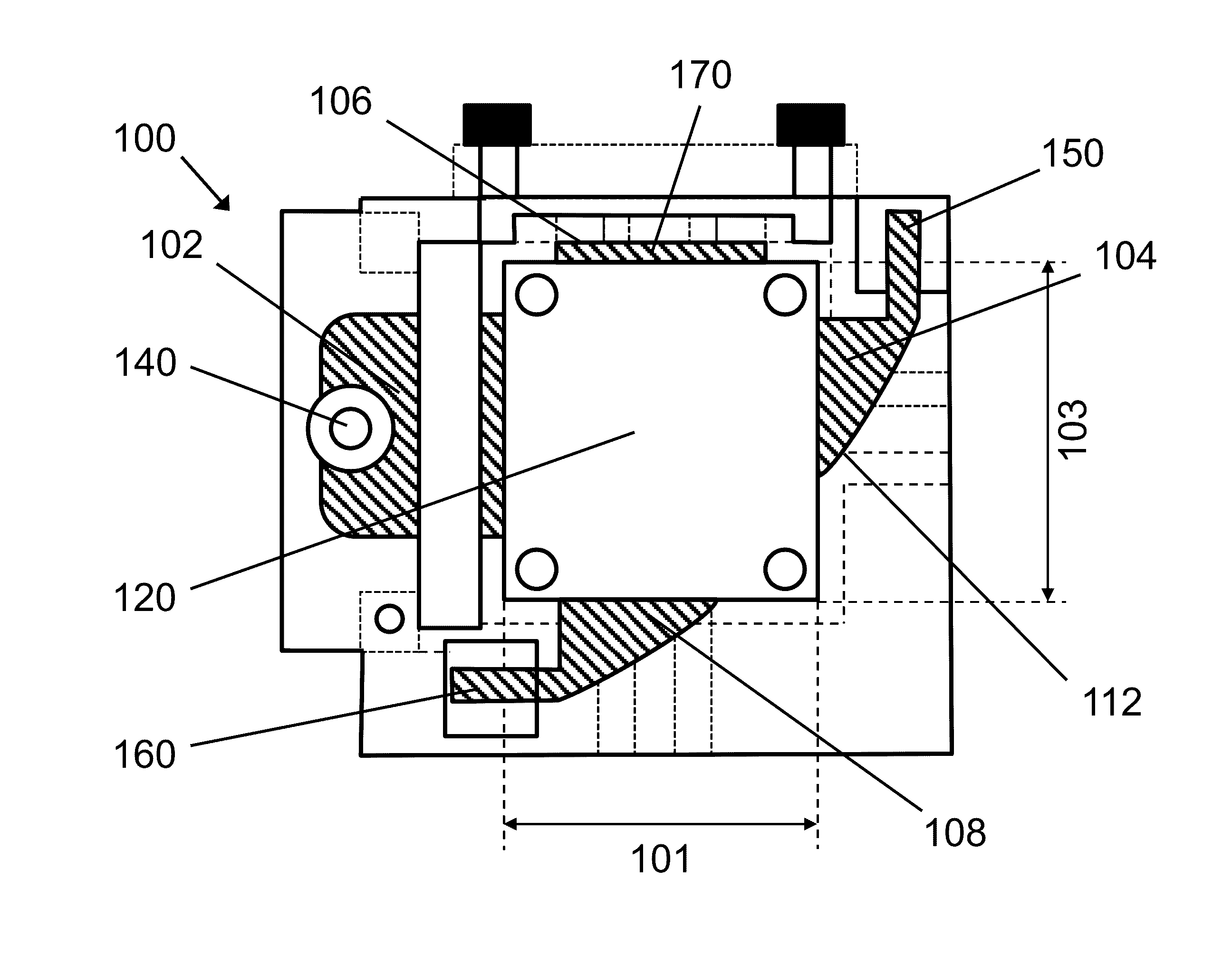
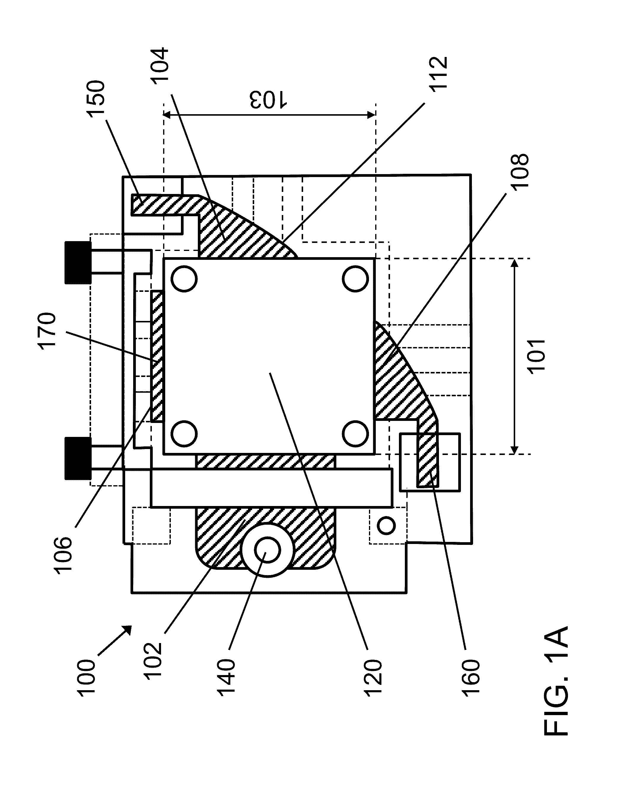
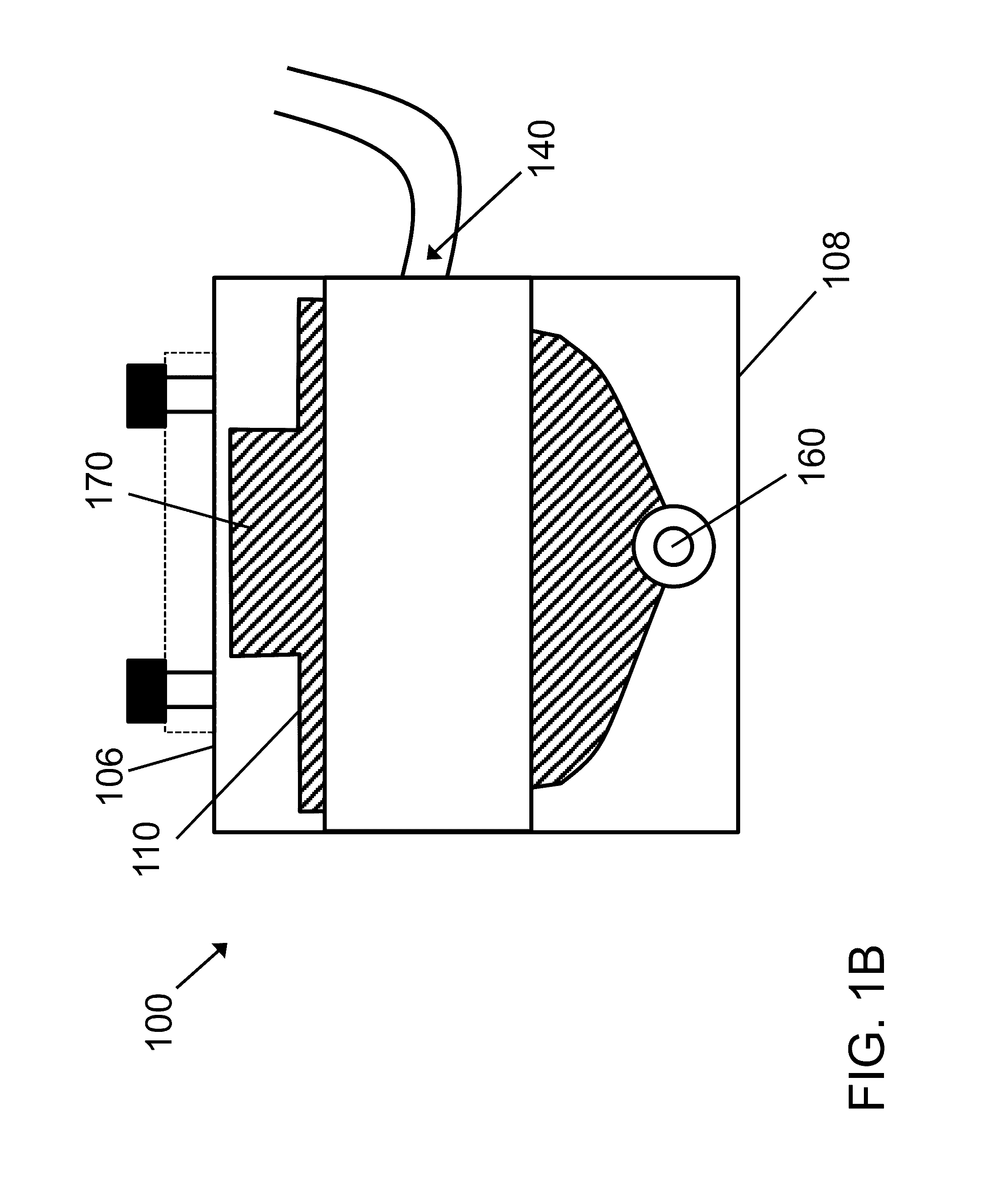
Acoustophoretic devices are disclosed. The devices include a flow chamber, an ultrasonic transducer, a reflector, an inlet, a filtrate outlet, a concentrate outlet, and optionally a lipid collection trap. The ultrasonic transducer and reflector create a multi-dimensional acoustic standing wave in the flow chamber that traps and separates red blood cells and/or lipids from blood. Concentrated red blood cells can be recovered via the concentrate outlet, the lipids can be recovered via the lipid collection trap, and the remaining blood can be recovered via the filtrate outlet. Methods for separating blood components (e.g., red blood cells, lipids, platelets, white blood cells) from blood are also disclosed. The red blood cells can undergo washing with a solvent to remove undesired admixtures. Cryoprotectants can be added or removed from the blood.

Description

CROSS-REFERENCE TO RELATED APPLICATIONS[0001]This application claims priority to U.S. Provisional Patent Application Ser. No. 62 / 214,567, filed on Sep. 4, 2015 and to U.S. Provisional Patent Application Ser. No. 62 / 371,829, filed on Aug. 7, 2016; and is also a continuation-in-part of U.S. patent application Ser. No. 13 / 866,584, filed on Apr. 19, 2013, which claimed priority to U.S. Provisional Patent Application Ser. No. 61 / 636,515, filed on Apr. 20, 2012, the disclosures of which are hereby fully incorporated herein by reference in their entireties.BACKGROUND[0002]Cardiopulmonary bypass surgery is a common procedure whereby the function of the heart and lungs are taken over by a pump system commonly called a heart-lung machine. Cardiopulmonary bypass surgery is commonly used in coronary bypass heart surgery due to the difficulty of operating on a beating heart. This surgical procedure is also used for the repair of cardiac valves, organ transplants, repair of large aneurysms, and o...

Claims


Application Information

Patent Timeline
Patent Type & Authority Applications(United States)
IPC IPC(8): A61M1/36B06B1/06H01L41/04B01D21/34B01D21/28
CPCA61M1/3678B01D21/34B06B1/0644H01L41/04B01D21/286A61M2202/0427A61M2202/0429A61M2202/0439A61M2202/0456B01D21/30B01D2221/10
Inventor GILMANSHIN, RUDOLFLIPKENS, BARTDUTRA, BRIANKENNEDY, DANIEL
Owner FLODESIGN SONICS
Why Eureka
Try Eureka