Echogenic probe

a technology of echogenic probes and probes, applied in the field of echogenic probes, can solve the problems of not including echogenic markers, rf cannulae, and shafts that are not curved, and achieve the effect of easy visualization and directed, and easy visualization and directed

Inactive Publication Date: 2017-02-23
COSMAN MEDICAL INC
View PDF6 Cites 6 Cited by
  • Summary
  • Abstract
  • Description
  • Claims
  • Application Information

AI Technical Summary

Benefits of technology

[0022]The present invention relates generally to the application of echogenic markers and a curved tip to a medical needle, including radiofrequency cannulae, injection needles, biopsy needles, microwave antennae, and spinal needles. An advantage of the present invention is that medical needles can be more easily visualized and directed in the human body by means of ultrasound guidance when the needle is inserted at a steep angle relative to the ultrasound beam.
[0023]The present invention relates generally to the application of echogenic markers to medical probes wherein multiple types of echogenic markers are applied to the same probe and the multiple types of echogenic markers have different spatial scale and angles. An advantage of the present invention is that medical needles can be more easily visualized and directed in the human body by means of ultrasound guidance for a wide range of probe insertion angles relative to the ultrasound transceiver.
[0024]In one aspect, a radiofrequency probe can have an echogenic feature.
[0025]In certain embodiments, the probe can have a curved tip. The probe can be a cannula, an electrode, or a unitized injection electrode. The probe can be tissue-piercing. The probe can have a stiff shaft. The probe can include a shaft is composed of metal. The probe can be a radiofrequency cannula with a bevel configured for placement in the epidural space. The probe can be a needle configured to introduce a catheter. The probe can have a distal and proximal end, and a first and a second indentation in a surface of the probe, wherein the first indentation includes a distal aspect having a first angle relative to the surface of the probe, and the second indentation includes a distal aspect having a second angle relative to the surface of the probe.
[0026]In another aspect, a needle can have a curved tip and an echogenic feature.
[0027]In certain embodiments, the needle includes a shaft is composed of metal. The needle can be a radiofrequency cannula, part of a unitized radiofrequency electrode, an epidural needle, or a spinal needle. The needle can be configured for effecting a nerve block. The needle can have a distal and proximal end, and a first and a second indentation in a surface of the needle, wherein the first indentation includes a distal aspect having a first angle relative to the surface of the needle, and the second indentation includes a distal aspect having a second angle relative to the surface of the needle.

Problems solved by technology

One limitation of the CC and RFK RF cannulae is that they do not include echogenic markers.
This has the limitation that the shaft is not curved.
This has the limitation that the shaft does not contain both echogenic markers and a curved tip.
This has the limitation that it is not a hollow shaft covered in part by electrical insulation and having echogenic markers.
One limitation of epidural needles in the prior art is that they do not have electrical insulation.
Another limitation of epidural needles in the prior art is that they cannot functional as radiofrequency cannulae with a defined active tip.
One limitation of echogenic tuohy needles in the prior art is that the shaft curvature is not configured for steering of the needle within tissue.
Another limitation of echogenic tuohy needles in the prior art is that they do not have a bend in their shafts that is 5 mm or more from their most distal point.
Another limitation of echogenic tuohy needles in the prior art is that they do not have electrical insulation along their shafts.
Another limitation of echogenic tuohy needles in the prior art is that they are not configured for radiofrequency lesioning.
In this particular example, the needle has a slight curve or bends 27 near the tip of the needle that defines that flat planar surface 26 . . . . The needle illustrated in FIG. 2D is sometimes referred to as a TUOHY needle or a needle having a TUOHY-type point.” One limitation of the art in Massengale is that the needle shaft is substantially straight.
One limitation of the art in Massengale is that the slight curve in the needle is not 5 mm or more from the distal point of the needle.
One limitation of the art in Massengale is that the needles cannot be rotated into a position that reduces the angle of incidence of incoming ultrasound waves over a substantial length of the needle, for example a length of 5 mm or more.
One limitation of the art in Massengale is that the needles shown are not RF cannulae.
For example, the shaft may have a non-linear shape including, but not limited to, a curved shape.” One limitation of the soft tissue tunneling devices disclosed in Massengale is that they are not needles with sharp tips.
One limitation of the soft tissue tunneling devices disclosed in Massengale is that they are not RF cannulae.
One limitation of the soft tissue tunneling devices disclosed in Massengale is that they are not configured to delivery RF energy for therapeutic purposes.
One limitation of this invention is that the echogenic probe has a straight shaft.
One limitation of this invention is that the echogenic needle has a straight shaft.
One limitation of this invention is that the ultrasound needle has a straight shaft.
One limitation of this invention is that the echogenic needle has a straight shaft.
Another limitation is that the needle is not a radiofrequency cannula.
Another limitation is that the needle is not a radiofrequency electrode.
Another limitation is that the needle is not a microwave antenna.
Another limitation is that the means of echogenic enhancement does not utilize both macroscopic depressions in the needle surface and microscopic roughing of the needle surface.

Method used


Image

  • Echogenic probe
  • Echogenic probe
  • Echogenic probe

Examples


Embodiment Construction

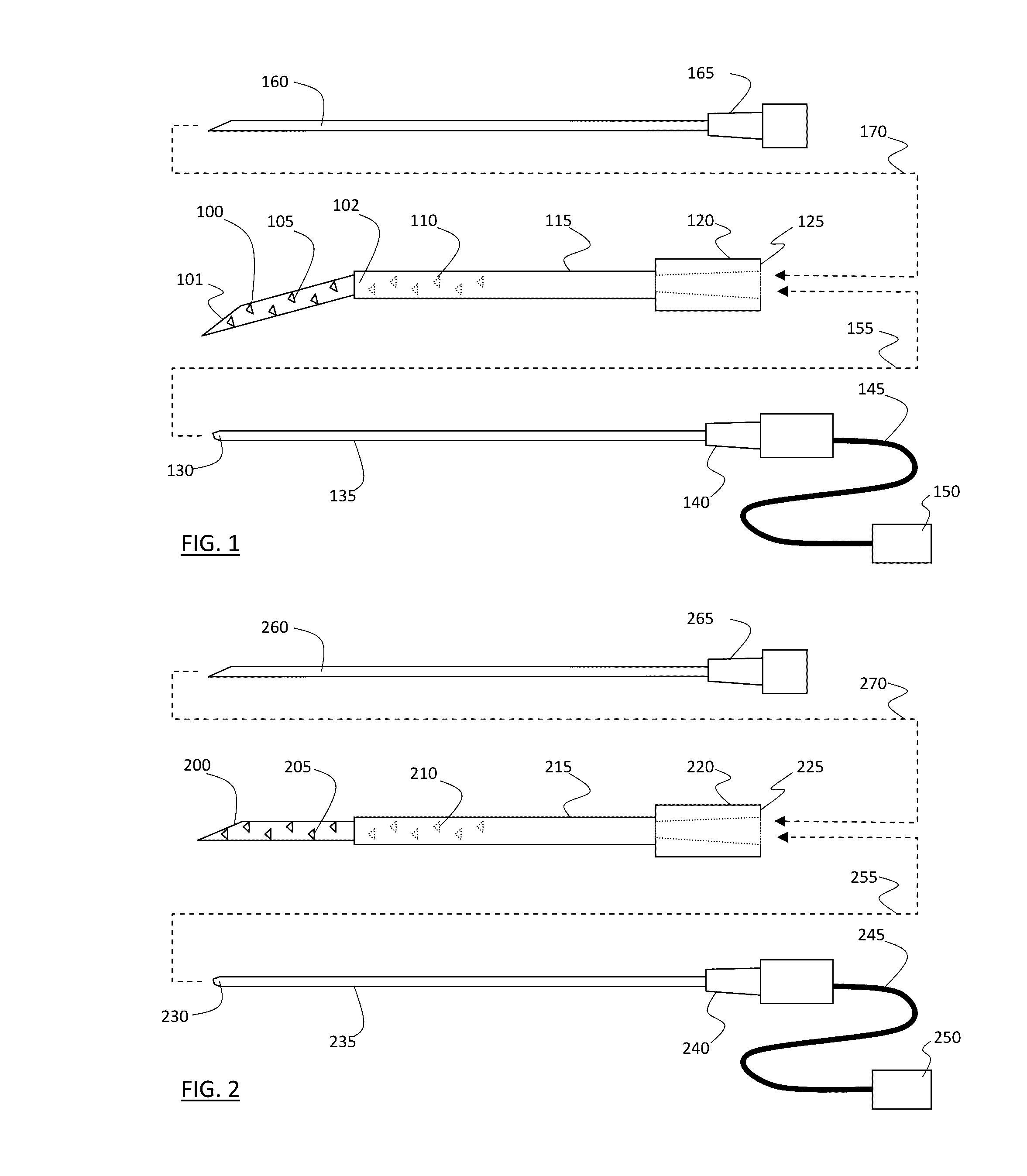
[0048]Referring to FIG. 1, a needle with shaft 100 is shown. The shaft 100 be substantially cylindrical. The needle can be hollow with an inner lumen. The inner lumen of the shaft 100 can open to the outside via a hole in the tip of the shaft 100 or holes along the shaft. The needle has a sharpened distal end, and is terminated by hub 120 at its proximal end. The needle can configured to penetrate biological tissue, such as the skin's surface, soft tissue around the spine, visceral organs, limbs, muscles, blood vessels, the liver, the kidney, the prostate, and other human and animal tissues. The needle's distal end can have a bevel 101. The needle can be a biopsy needle. The needle's distal end 101 can have a tissue-piercing geometry, such as a chiba tip. The needle's distal end 101 can have a rounded tip and stiff shaft capable of piecing tissue. The needle's distal end 101 can have an epidural geometry, such as a tuohy tip. The needle can be radiofrequency cannula. The needle can ...


PUM


Abstract

Echogenic markers can be applied to probes such as medical needles, including radiofrequency cannulae, injection needles, biopsy needles, microwave antennae, and spinal needles, among others. For example, in certain embodiments, the probes may have a distal end, a proximal end, a shaft, and an echogenic feature in the form of one or more indentations on the shaft. In certain embodiments, the probes may have a first echogenic feature in the form of an indentation in a surface of the probe and a second echogenic feature in the form of a roughening of the surface of the probe.

Description

PRIORITY CLAIM[0001]This application claims priority to U.S. Provisional Application No. 61 / 683,190, filed Aug. 14, 2012, which is incorporated by reference in its entirety.TECHNICAL FIELD OF THE INVENTION[0002]The invention relates generally to probes used in medical procedures. The invention relates more specifically to means of enhancing the ultrasound image of probes used in medical procedures. The invention relates more specifically to field therapy.BACKGROUND OF THE INVENTION[0003]The use of radiofrequency (RF) generators and electrodes to be applied to tissue for pain relief or functional modification is well known. For example, the RFG-3B RF lesion generator of Radionics, Inc., Burlington, Mass. and its associated electrodes enable electrode placement of the electrode near target tissue and heating of the target tissue by RF power dissipation of the RF signal output in the target tissue. For example, the G4 generator of Cosman Medical, Inc., Burlington, Mass. and its associa...

Claims


Application Information

Patent Timeline
Patent Type & Authority Applications(United States)
IPC IPC(8): A61M25/01A61B18/14A61B18/18
CPCA61M25/0105A61B18/18A61B18/1477A61B2090/3925A61M25/0108
Inventor COSMAN, ERIC R.
Owner COSMAN MEDICAL INC
Why Eureka
Try Eureka