Detector for x-rays with high spatial and high spectral resolution

a spectral resolution and x-ray technology, applied in the field of detection and spectral analysis of x-rays, can solve the problems of weak signals, inability to detect and analyze x-rays, and inability to detect x-rays in time,

Active Publication Date: 2017-02-23
SIGRAY INC
View PDF2 Cites 34 Cited by
  • Summary
  • Abstract
  • Description
  • Claims
  • Application Information

AI Technical Summary

Benefits of technology

[0012]In embodiments where spatial sensitivity is provided by one or more apertures, the energy sensitive x-ray detection system may include a spectrally sensitive but not position sensitive detector, such as a silicon drift detector (SDD), a silicon lithium (Si(Li)) detector, or any type of x-ray detector used in combination with an x-ray wavelength-dispersive component, such as a diffractive crystal or synthetic multilayer. In some other embodiments, the detector system may comprise a diffractive element (e.g. crystal) that splits and diffracts the x-ray beam into multiple x-ray beams of different energies placed upstream of a position sensitive x-ray detector. In such embodiments, the aperture(s) are used for position sensitivity by further spatially refining the detected emitting volume of interest. Moreover, in some embodiments, the aperture(s) can be moved, which allows spatial mapping of different sub-volumes within the x-ray emitting volume.

Problems solved by technology

Several limitations exist with such approaches.
As a consequence, resolution is still inherently limited to the “focal” spot of the polycapillary.
And, although optics with smaller focal spots may be used, the collection efficiency of such smaller optics drops significantly, resulting in weak signals and very long acquisition times. Additionally, absolute quantification of material composition is difficult or impossible due to the optics not being achromatic.
Other approaches include, the use of apertures or small non-imaging monocapillary x-ray optics, but these dramatically reduce the signal detected.

Method used


Image

  • Detector for x-rays with high spatial and high spectral resolution
  • Detector for x-rays with high spatial and high spectral resolution
  • Detector for x-rays with high spatial and high spectral resolution

Examples


Embodiment Construction

1. A Basic Embodiment

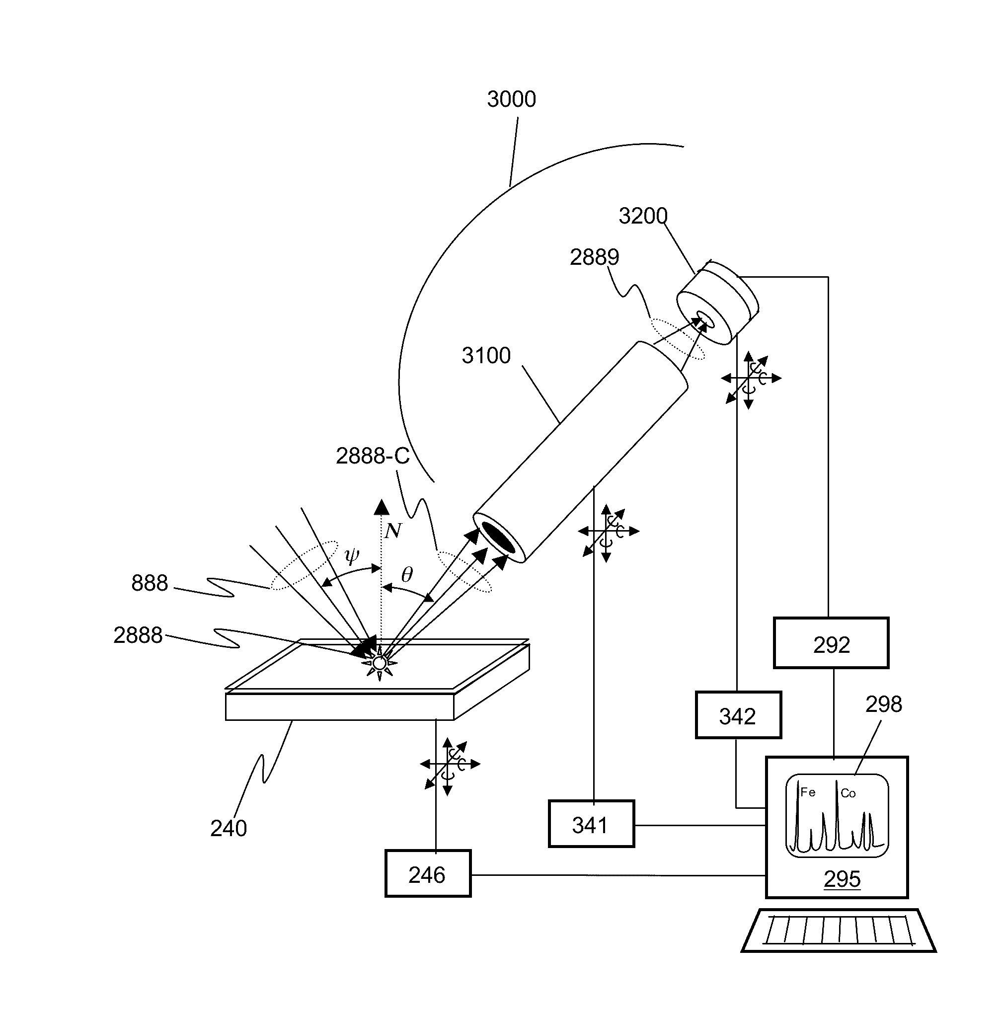
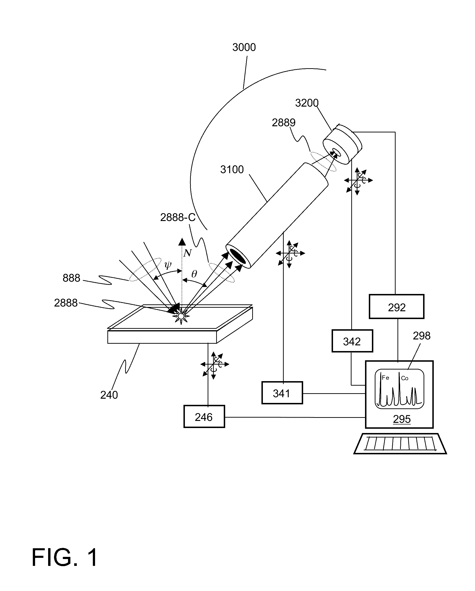
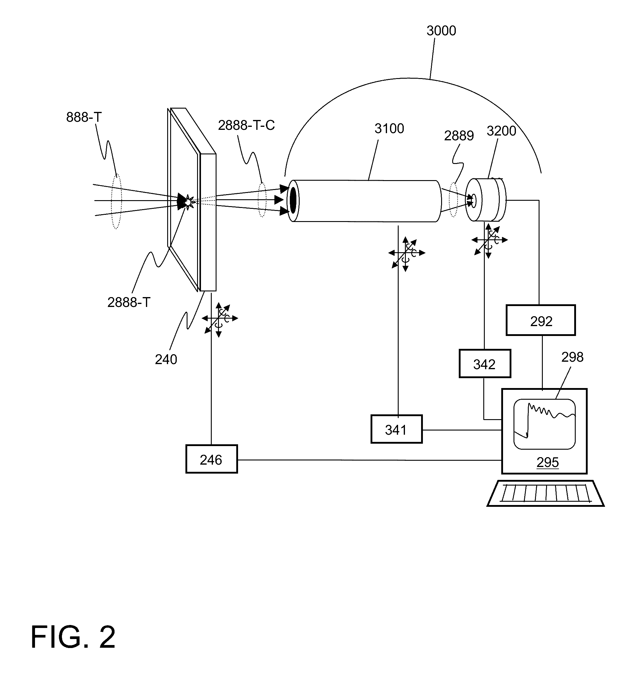
[0030]The invention disclosed herein relates to a method and apparatus for x-ray detection with high spatial resolution and spectral energy resolution. Spatial resolution is achieved in part through the use of achromatic x-ray imaging optics between a object and a detector system placed at the image plane capable of spectral resolution while spatially resolving the image formed by the optics. Spectral resolution is achieved through the use of energy sensitive detectors or by using other x-ray spectroscopy techniques based on energy-selective elements, such as crystal monochromators, filters, or multilayer reflectors. Spatial sensitivity is achieved either through use of a spatially selective aperture or an array arrangement of the energy-resolving elements.

[0031]FIG. 1 illustrates a schematic of the basic elements of a simple embodiment of the invention. An x-ray spectrometer system 3000 is placed to collect x-rays 2888 emitted within a sub-volume of an object 2...


PUM

PropertyMeasurementUnit
full-width half maximumaaaaaaaaaa
thicknessaaaaaaaaaa
angleaaaaaaaaaa

Abstract

An x-ray spectrometer system comprising an x-ray imaging system with at least one achromatic imaging x-ray optic and an x-ray detection system. The optical train of the imaging system is arranged so that its object focal plane partially overlaps an x-ray emitting volume of an object. An image of a portion of the object is formed with a predetermined image magnification at the x-ray detection system. The x-ray detection system has both high spatial and spectral resolution, and converts the detected x-rays to electronic signals. In some embodiments, the detector system may have a small aperture placed in the image plane, and use a silicon drift detector to collect x-rays passing through the aperture. In other embodiments, the detector system has an energy resolving pixel array x-ray detector. In other embodiments, wavelength dispersive elements may be used in either the optical train or the detector system.

Description

CROSS-REFERENCE TO RELATED APPLICATIONS[0001]This Patent Application claims the benefit of U.S. Provisional Patent Application No. 62 / 206,839, filed Aug. 18, 2015 and entitled “METHOD AND APPARATUS FOR X-RAY SPECTROSCOPY WITH HIGH SPATIAL RESOLUTION”, which is incorporated herein by reference in its entirety.STATEMENT REGARDING FEDERALLY SPONSORED RESEARCH[0002]This Application relates to work supported in part by grant number National Science Foundation (NSF) grant numbers IIP-1448727 and IIP-1556020, both entitled “Development of a Dual Energy Micro-focused X-ray Excitation Beam for Chemical Analysis and Materials Characterization”. The government may have certain rights to the invention.FIELD OF THE INVENTION[0003]The invention disclosed herein relates to a method and apparatus for the detection and spectral analysis of x-rays emerging from specific locations within an object, and the subsequent inference of certain properties of the object, such as a mapping of the material comp...

Claims


Application Information

Patent Timeline
Patent Type & Authority Applications(United States)
IPC IPC(8): G01N23/22G01N23/223G01N23/20
CPCG01N23/2206G01N2223/423G01N23/223G01N23/20058G01N23/04G01N2223/052G01N2223/056G01N2223/076
Inventor YUN, WENBINGLEWIS, SYLVIA JIA YUNKIRZ, JANOSSTRIPE, BENJAMIN DONALD
Owner SIGRAY INC
Why Eureka
Try Eureka