Method for cleaning a process chamber

Inactive Publication Date: 2017-03-09
INTERUNIVERSITAIR MICRO ELECTRONICS CENT (IMEC VZW) +1
View PDF4 Cites 1 Cited by
  • Summary
  • Abstract
  • Description
  • Claims
  • Application Information

AI Technical Summary

Benefits of technology

[0005]It is an object of embodiments of the present disclosure to provide a met

Problems solved by technology

This can lead to sample contamination when for instance some of these non-volatile deposits re-depose on a next sample.
Also, process drift often occurs due to re-sputtering of those non-volatile deposits.
Most of the commonly used cleaning procedures are however not sufficient in removing the chamber conta

Method used


Image

  • Method for cleaning a process chamber
  • Method for cleaning a process chamber
  • Method for cleaning a process chamber

Examples


Embodiment Construction

[0064]The present disclosure will be described with respect to particular embodiments and with reference to certain drawings but the disclosure is not limited thereto but only by the claims. The drawings described are only schematic and are non-limiting. In the drawings, the size of some of the elements may be exaggerated and not drawn on scale for illustrative purposes. The dimensions and the relative dimensions do not correspond to actual reductions to practice of the disclosure.

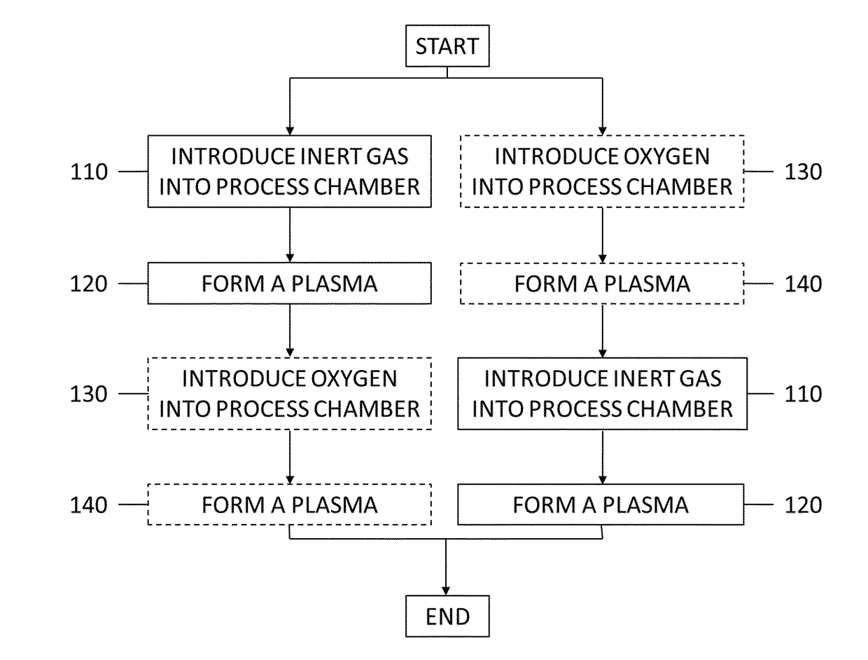
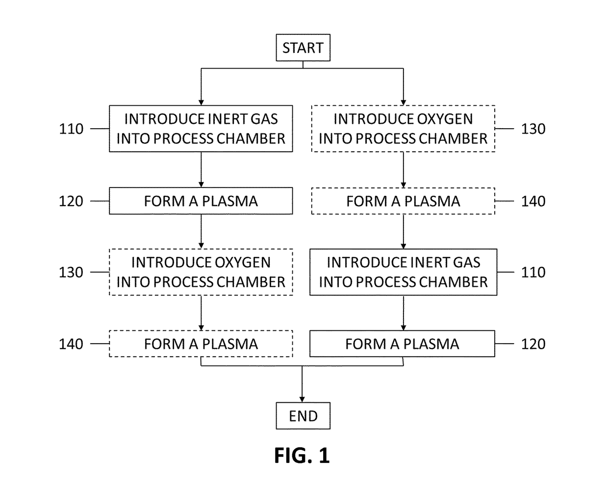
[0065]FIG. 1 is a flowchart of the method operations for cleaning a process chamber of a capacitively coupled plasma reactor in accordance with an embodiment of the present disclosure. In an operation 110“introduce inert gas into process chamber” a gas comprising 80-100% in volume of inert gas is introduced into the process chamber, wherein said inert gas is selected from the group consisting of neon, argon, krypton, xenon and combinations thereof.

[0066]In an operation 120“form a plasma” a plasma is formed...


PUM

PropertyMeasurementUnit
Fractionaaaaaaaaaa
Pressureaaaaaaaaaa
Poweraaaaaaaaaa

Abstract

The disclosure relates to a method of cleaning a process chamber of a capacitively coupled plasma reactor, the method comprising: a) Introducing a gas comprising 80-100% in volume of inert gas into the process chamber, wherein said inert gas is selected from the group consisting of neon, argon, krypton, xenon and combinations thereof; and b) Forming a plasma from said inert gas, thereby cleaning said process chamber.

Description

FIELD OF THE DISCLOSURE[0001]The present disclosure relates to the field of plasma process chamber cleaning methods. More specifically it relates to a method of cleaning a process chamber of a capacitively coupled plasma reactor after dry etching.BACKGROUND OF THE DISCLOSURE[0002]Plasma process chambers, and in particular those used for etching, often see their walls and / or electrode(s) covered by non-volatile deposits such as etching byproducts. This can lead to sample contamination when for instance some of these non-volatile deposits re-depose on a next sample. Also, process drift often occurs due to re-sputtering of those non-volatile deposits. It is therefore necessary for many applications that the plasma chamber remains free of such non-volatile material deposits. Making sure that the chamber is clean and keeping the chamber in this stable condition is therefore important. Most of the commonly used cleaning procedures are however not sufficient in removing the chamber contami...

Claims


Application Information

Patent Timeline
IPC IPC(8): H01J37/32B08B9/08B08B7/00
CPCH01J37/32862B08B7/0035H01J2237/334H01J37/32091H01J37/32715B08B9/08C23C16/4405
Inventor TAHARA, SHIGERURADISIC, DUNJA
Owner INTERUNIVERSITAIR MICRO ELECTRONICS CENT (IMEC VZW)
Why Eureka
Try Eureka