Long-life, high-efficiency laser apparatus having plurality of laser diode modules

Active Publication Date: 2017-03-09
FANUC LTD
View PDF3 Cites 3 Cited by
  • Summary
  • Abstract
  • Description
  • Claims
  • Application Information

AI Technical Summary

Benefits of technology

[0013]There is therefore a need to develop a laser apparatus that is driven so as to always achieve maximum electrical to optical conversion efficiency, with provisions made to avoid concentrating the driving load on a limited number of oscillator modules and to extend the life of the laser apparatus as long as possible.
[0014]According to one embodiment of the present invention, there is provided a laser apparatus which includes a plurality of laser diode module groups each containing at least one laser diode module, and a plurality of power supply units each for supplying a driving current to a corresponding one of the plurality of laser diode module groups, and which provides a laser light source or a pumping light source for laser oscillation by collecting laser beam from the plurality of laser diode module groups. The laser apparatus comprises a driving current supply circuit network, a control unit, a first recording unit, and a first calculating unit. The driving current supply circuit network is capable of injecting the driving currents from the plurality of power supply units into the plurality of respective laser diode module groups, independently for each of the plurality of laser diode module groups. The control unit controls the driving currents to be injected from the plurality of power supply units into the plurality of respective laser diode module groups, independently for each of the plurality of laser diode module groups. The first re

Problems solved by technology

However, with the conventional art, it has not always been possible to drive such laser apparatus under conditions of the highest electrical to optical conversion efficiency over a wide optical output power command range.
Furthermore, in the case of a laser apparatus constructed from a plurality of oscillator modules in order to achieve high output power, if the driving condition is changed for each oscillator modu

Method used


Image

  • Long-life, high-efficiency laser apparatus having plurality of laser diode modules
  • Long-life, high-efficiency laser apparatus having plurality of laser diode modules
  • Long-life, high-efficiency laser apparatus having plurality of laser diode modules

Examples


Example

First Embodiment

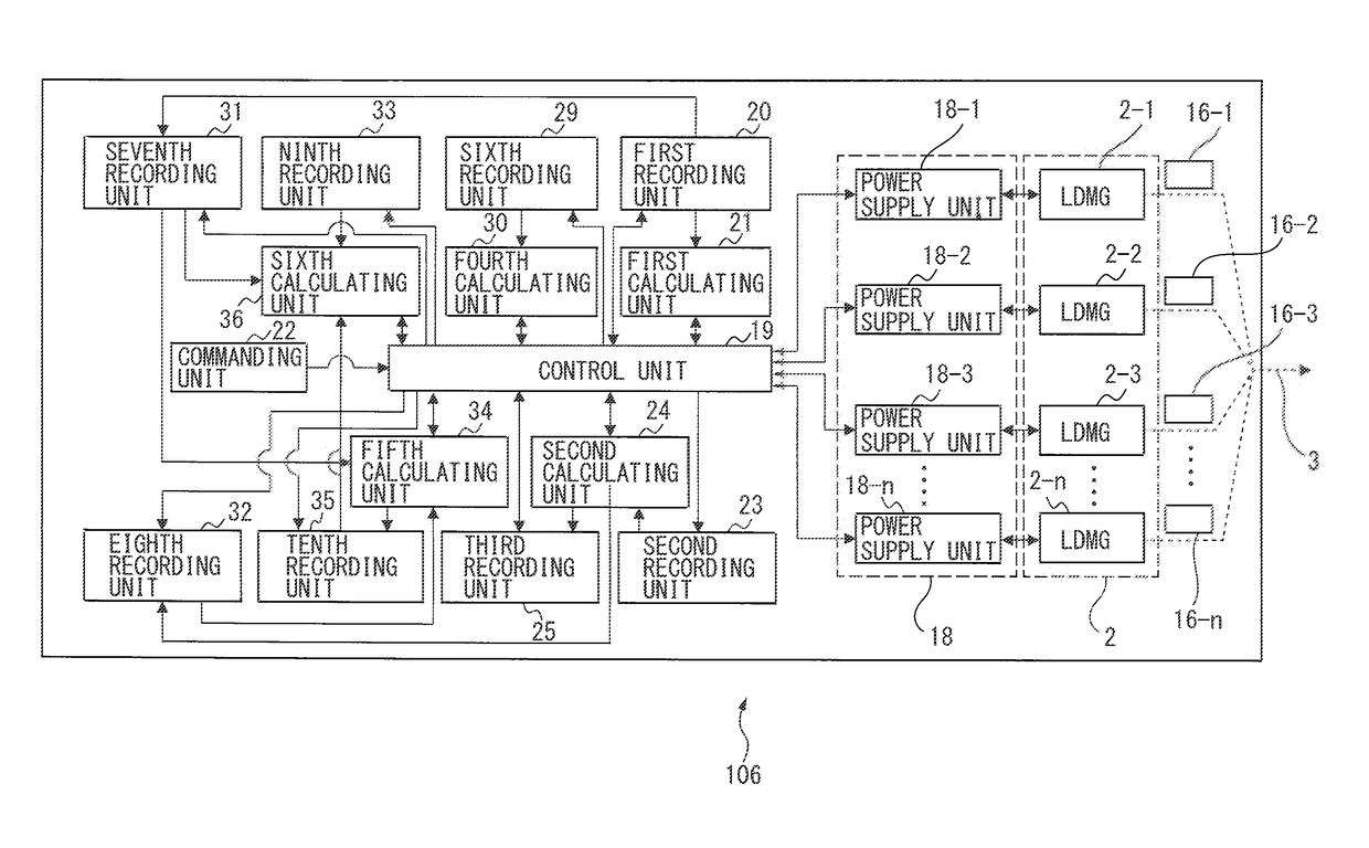
[0040]FIG. 9 is a schematic diagram showing the configuration of a laser apparatus according to a first embodiment of the present invention. The laser apparatus 101 of the present embodiment is a laser apparatus which includes a plurality of laser diode module groups 2 each containing at least one laser diode module, and a plurality of power supply units 18 each for supplying a driving current to a corresponding one of the plurality of laser diode module groups 2, and which provides a laser light source or a pumping light source for laser oscillation by collecting laser beam 3 from the plurality of laser diode module groups 2. The laser apparatus 101 comprises a driving current supply circuit network 17, a control unit 19, a first recording unit 20, and a first calculating unit 21. The driving current supply circuit network 17 is capable of injecting the driving currents from the plurality of power supply units 18 into the plurality of respective laser diode module g...

Example

Second Embodiment

[0050]FIGS. 11A and 11B are diagrams for explaining a laser apparatus according to a second embodiment of the present invention, showing an example of a pulse output command waveform 13 applied to the laser apparatus, an example of a driving current waveform 14 allocated to each individual laser diode module, and an example of an optical output power waveform 15 output from each individual laser diode module. A description will be given for the case where the laser beam output power command 13 to the laser apparatus is a pulse output command such that the optical output power alternates cyclically between a high output power level and a low output power level, as shown in FIGS. 11A and 11B. In this case, the control unit allocates the driving currents to the plurality of respective laser diode module groups so that the plurality of laser diode module groups as a whole can achieve maximum or substantially maximum electrical to optical conversion efficiency under cond...

Example

Third Embodiment

[0053]FIG. 12 is a schematic diagram showing the configuration of a laser apparatus for explaining a laser apparatus 102 according to a third embodiment of the present invention.

[0054]The laser apparatus 102 according to the third embodiment of the present invention comprises a second recording unit 23, a second calculating unit 24, and a third recording unit 25. The second recording unit 23 records a data table of an acceleration-deceleration coefficient A(I) for driving-current-related life consumption speed. The acceleration-deceleration coefficient A(I) is obtained by dividing the life expected of the plurality of laser diode module groups 2 when the plurality of laser diode module groups 2 are driven with a standard driving current Is by the life expected of the plurality of laser diode module groups 2 when the plurality of laser diode module groups 2 are driven with a driving current I. The second calculating unit 24 calculates a time-integrated value=∫tatbA(I(...


PUM


Abstract

A laser apparatus includes laser diode module groups (LDMGs) and power supply units and provides a laser light source by collecting laser beam from the LDMGs, and comprises: a driving current supply circuit network for injecting the driving currents into the respective LDMGs, independently; a control unit which controls the driving currents independently; a first recording unit in which are recorded data representing a relationship between the driving current and optical output power, and data representing a relationship between the driving current and drive voltage; and a first calculating unit which calculates the driving currents to be allocated to the LDMGs so as to achieve maximum electrical to optical conversion efficiency, wherein the control unit allocates the driving currents to the LDMGs in accordance with the results calculated by the first calculating unit so that the LDMGs as a whole can achieve maximum electrical to optical conversion efficiency under conditions.

Description

[0001]This application is a new U.S. patent application that claims benefit of JP 2015-177969 filed on Sep. 9, 2015, the content of 2015-177969 is incorporated herein by reference.BACKGROUND OF THE INVENTION[0002]1. Field of the Invention[0003]The present invention relates to a laser apparatus, and in particular to a laser apparatus that uses a plurality of laser diode modules to provide a light emitting source or a pumping light source.[0004]2. Description of the Related Art[0005]Many high-power laser apparatuses are equipped with a plurality of laser light source units in order to achieve high output power, and a variety of driving methods have been reported in the conventional art (for example, refer to Japanese Patent No. 5729107, hereinafter referred to as “patent document 1”, Japanese Patent No. 4341600, hereinafter referred to as “patent document 2”, and Japanese Unexamined Patent Publication No. 2012-124304, hereinafter referred to as “patent document 3”).[0006]Patent docume...

Claims


Application Information

Patent Timeline
IPC IPC(8): H01S5/0683H01S5/042H01S5/40
CPCH01S5/0683H01S5/042H01S5/4025H01S5/06H01S3/0675H01S3/094011H01S3/094076H01S3/09415H01S5/0021H01S5/0617H01S5/06216H01S5/06835H01S5/4012
Inventor TAKIGAWA, HIROSHIMACHIDA, HISATADA
Owner FANUC LTD
Why Eureka
Try Eureka