
Dc/dc converter and switching power supply

Active Publication Date: 2017-03-09
ROHM CO LTD
View PDF5 Cites 39 Cited by
  • Summary
  • Abstract
  • Description
  • Claims
  • Application Information

AI Technical Summary

Benefits of technology

The present invention provides a DC-DC converter with a soft-start circuit that can generate a gradual increase in voltage, an error amplifier that can compare the output voltage with the reference voltage and generate an error signal, a variable output current generator that can generate a current proportional to the soft-start input voltage, a constant-current source that can generate a bias current, an oscillator that can generate a rectangular-wave signal, a slope circuit that can generate a slope signal based on the oscillator signal, a PWM comparator that can generate a pulse-width modulated signal, and a control circuit that can turn on and off transistors alternately based on the pulse-width modulated signal. The invention also provides a switching power supply device with a driving circuit that can generate an output voltage by stepping down an input voltage, an error amplifier that can compare the output voltage with a feedback voltage and generate an error signal, an oscillation circuit that can generate an ON signal at a predetermined switching frequency, a slope voltage generation circuit that can generate a slope voltage in synchronization with the ON signal, a comparison circuit that can generate an OFF signal by comparing the error voltage with the slope voltage, and a logic circuit that can generate an ON / OFF control signal based on the ON and OFF signals. The invention also provides a switching power supply device with a driving circuit that can generate an output voltage by using an output transistor. The invention solves the problem of overcurrent protection and ensures a smooth start-up of the power supply device.

Problems solved by technology

A reference voltage generator like this requires a complicated circuit configuration.
However, when the frequency is switched, an overshoot occurs in the output voltage.
Moreover, the use of the frequency divider results in a complicated circuit configuration.
Moreover, the use of the counter results in a complicated circuit configuration.
This inconveniently results in increased output ripples at start-up.
Third Problem: As for the third conventional technology, in conventional switching power supply devices, the offset level of a slope voltage is fixed.
This inconveniently results in the magnitude of the load current at the time of switching to a light-load mode varying depending on input / output settings (the difference between the input voltage and the output voltage).

Method used


Image

  • Dc/dc converter and switching power supply
  • Dc/dc converter and switching power supply
  • Dc/dc converter and switching power supply

Examples


Embodiment Construction

[0058]First Embodiment: A first embodiment of the present invention will be described below with reference to the relevant drawings.

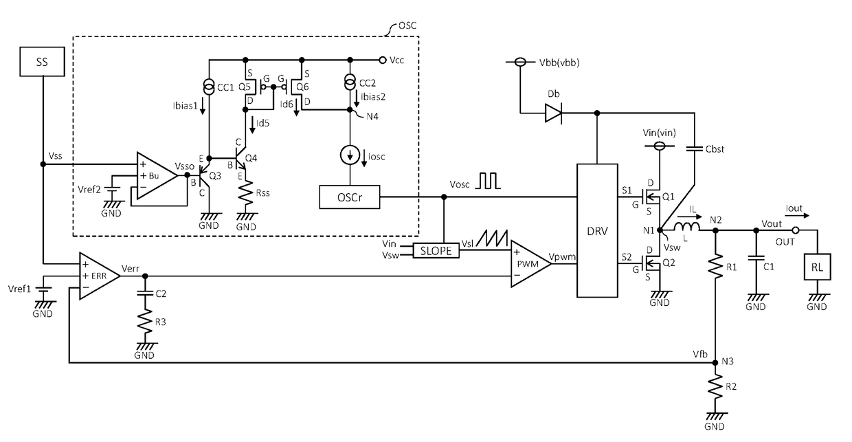
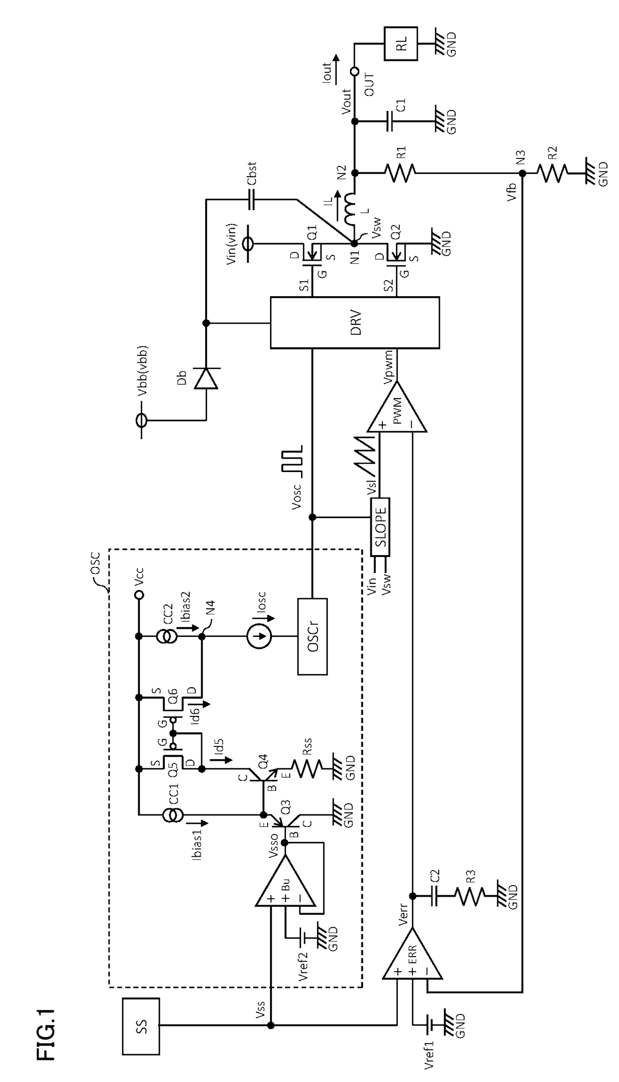
[0059]FIG. 1 is a circuit diagram of a DC-DC converter including a soft-start circuit according to a first embodiment of the present invention. The DC-DC converter in FIG. 1 is a synchronous-rectification step-down DC-DC converter.

[0060]In FIG. 1, the DC-DC converter is composed of a control circuit DRV, a first transistor Q1, a second transistor Q2, an inductor L, a capacitor C1, a capacitor C2, resistors R1 to R3, an error amplifier ERR, a slope circuit SLOPE, a PWM comparator PWM, a soft-start circuit SS, and an oscillation circuit OSC. The inductor L has an inductance of, for example, 0.47 μH to 47 μH. The capacitor C1 has a capacitance of, for example 10 μF to 1000 μf. The capacitor C2 has a capacitance of, for example 1000 pF to 10 nF. The resistor R3 has a resistance of, for example, 1 kΩ to 200 kΩ.

[0061]The first and second transistors Q1 and Q2...


PUM


Abstract

A DC / DC converter has: a soft-start circuit generating a soft-start input voltage increasing gradually; an error amplifier generating an error signal by comparing an output voltage or a feedback voltage with a reference voltage or the soft-start input voltage, whichever is lower; a variable current generator generating a variable current proportional to the soft-start input voltage or a soft-start output voltage; a constant current source generating a bias current; an oscillator generating a rectangular-wave signal whose frequency varies linearly with a soft-start current which is the sum of the variable current and the bias current; a slope circuit generating a slope signal based on the rectangular-wave signal; a PWM comparator generating a PWM signal based on the error signal and the slope signal; and a control circuit switching transistors alternately based on the PWM signal. Through switching operation of the transistors, an input voltage is converted into the output voltage.

Description

CROSS-REFERENCE TO RELATED APPLICATIONS[0001]This application is based on the following Japanese patent applications, the contents of all of which are hereby incorporated by reference:[0002](1) Japanese Patent Application filed as No. 2015-176689 (on Sep. 8, 2015)[0003](2) Japanese Patent Application filed as No. 2015-182596 (on Sep. 16, 2015)[0004](3) Japanese Patent Application filed as No. 2015-182597 (on Sep. 16, 2015)[0005](4) Japanese Patent Application filed as No. 2016-156485 (on Aug. 9, 2016)BACKGROUND OF THE INVENTION[0006]1. Field of the Invention[0007]The present invention relates to DC-DC converters including a soft-start circuit for use in switching power supplies, and to switching power supplies.[0008]2. Description of Related Art[0009]First Conventional Technology: DC-DC converters including a soft-start circuit are used in electronic appliances, OA (office automation) appliances, etc. When an electronic appliance or the like starts up, the provision of a soft-start ...

Claims


Application Information

Patent Timeline
IPC IPC(8): H02M3/158H02M1/32H02M1/08H02M1/36
CPCH02M3/158H02M1/36H02M2001/0009H02M1/08H02M1/32G05F1/46H02M1/0009
Inventor GUAN, SHIDONGWACHI, TAKATSUGUHIGASHIDA, YOSHIOYOSHIDA, TAKEHIRO
Owner ROHM CO LTD
Learn More