Apparatus and method for assessing tissue treatment

a tissue and apparatus technology, applied in the field of tissue monitoring apparatus, can solve the problems of difficult or flawed methods incorporating optical spectra collection, standard ablation catheters in cardiac space are typically inherently unstable in operation, and the method incorporating diffuse reflectance spectroscopy (dr) in the catheter would suffer from these issues

Active Publication Date: 2017-03-16
LIM BERNARD BOON CHYE
View PDF5 Cites 13 Cited by
  • Summary
  • Abstract
  • Description
  • Claims
  • Application Information

AI Technical Summary

Benefits of technology

[0023]The catheter may include one or more apertures wherein the optical emitting and receiving elements are configured to emit and receive optical radiation through the apertures.
[0024]In one embodiment the catheter's distal portion includes a basket

Problems solved by technology

Standard ablation catheters in a cardiac space are typically inherently unstable in operation.
Methods incorporating the collection of optical spectra are difficult or flawed due to catheter motion and inconsistent contact pressure.
Any method incorporating diffuse reflectance spectroscopy (DRS) in a catheter would suffer from these issues.
Furthermore, DRS deployed with a standard offset between illuminating and collecting fibers will only penetrate tissue to small penetration depths.
Standard catheters cannot achieve a sufficient spatial offset between illuminating and receiving optic fibers due to the limited length of the distal tip of the catheter that is in contact with the heart and therefore cannot exploit a sufficient spatial offset to achieve greater penetration depths.
Insufficient energy and duration will lead to ineffective lesions which result in local tissue swelling and edema which will prevent further effective completion of the lesion at the same location.
Checking for lesion characteristics after the first ablation is therefore ineffective.
On the other hand, applying too much energy for too long can lead to collateral damage like coagulum formation and damage to surrounding structures.
On the other hand, applying too much energy creates collateral damage to the heart.
Unfortunately, it is also very hard to measure, and even worse, the doctor has to get it right the first time.
This is where the prior art fails.
In particular the prior art is unable to provide a catheter that can examine dee

Method used


Image

  • Apparatus and method for assessing tissue treatment
  • Apparatus and method for assessing tissue treatment
  • Apparatus and method for assessing tissue treatment

Examples


Embodiment Construction

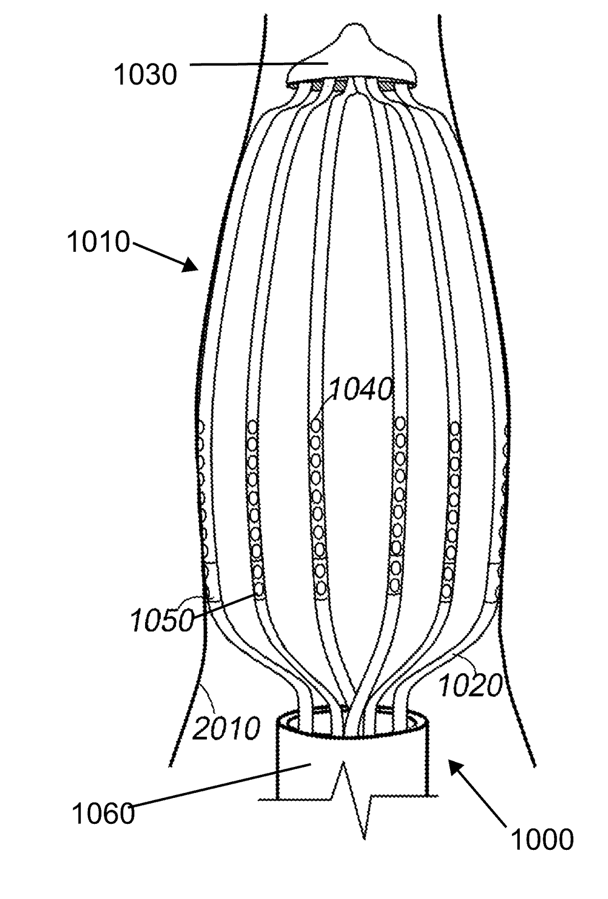
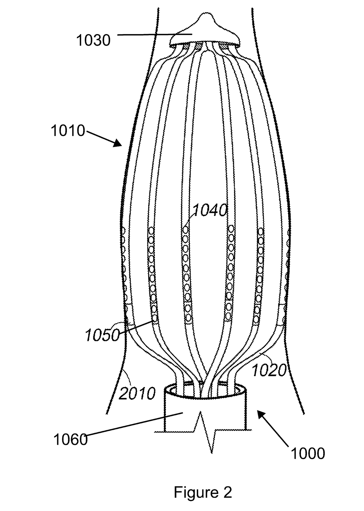
[0059]In general, the invention comprises a medical procedure and corresponding medical devices for generating optical sensing data indicative of an optical property of a tissue. More specifically, the invention relates to a tissue monitoring apparatus, a tissue monitoring method and an ablation lesion monitoring, measuring, and controlling algorithm incorporating diffuse reflectance spectroscopy (DRS) and / or Arrhenius model thermal denaturation kinetics for determining the characteristics of the lesion, nerves, or the tissue, especially for identifying the completion of the ablation lesion. The invention pertains to a device for and method of real time monitoring of lesion formation as ablation is being carried out.

Setting Appropriate End Points for Ablation

Atrial Fibrillation Ablation

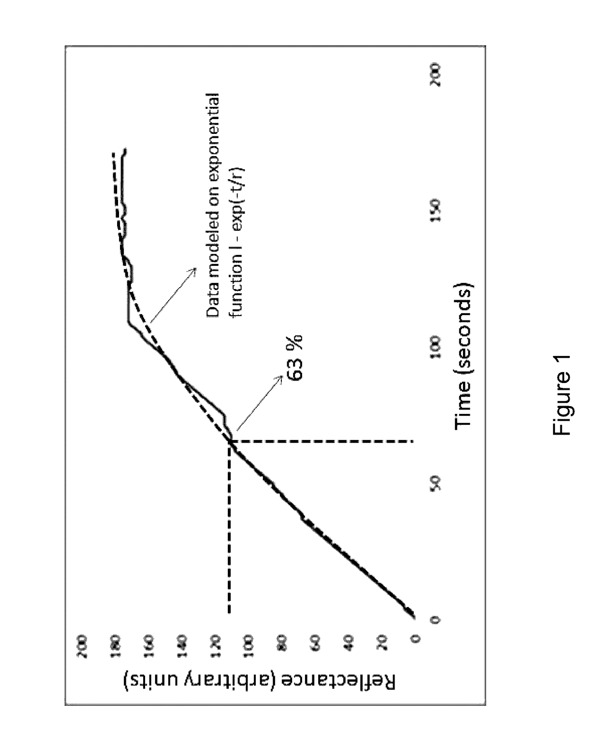
[0060]As tissue is undergoing heat denaturation, for example, by ablation, the tissue's optical properties change. Beauvoit et al. reported that the mitochondrial compartment is the primary cause of l...


PUM


Abstract

The invention relates to a tissue monitoring apparatus, a tissue monitoring method and an ablation lesion monitoring, measuring, and controlling automated algorithm incorporating diffuse reflectance spectroscopy (DRS) and/or Arrhenius model thermal denaturation kinetics for determining the characteristics of the lesion or the tissue, especially for identifying the transmurality of the ablation lesion. The invention pertains to a device for and method of real time monitoring of lesion formation as ablation is being carried out.

Description

CROSS REFERENCE TO RELATED APPLICATIONS[0001]This application claims the benefit of priority to U.S. patent application Ser. No. 13 / 945,749, filed Jul. 18, 2013, and to its parent, U.S. Provisional Application No. 61 / 673,025 filed Jul. 18, 2012, the entire disclosures of which are hereby incorporated by reference.BACKGROUND OF THE INVENTION[0002]Field of the Invention[0003]The invention relates to a tissue monitoring apparatus, a tissue monitoring method and an ablation lesion monitoring, measuring, and controlling algorithm incorporating diffuse reflectance spectroscopy (DRS) and / or Arrhenius model thermal denaturation kinetics for determining the characteristics of the lesion or the tissue, especially for identifying the transmurality of the ablation lesion. The invention pertains to a device for and method of real time monitoring of lesion formation as ablation is being carried out.[0004]Background Art[0005]Standard ablation catheters in a cardiac space are typically inherently u...

Claims


Application Information

Patent Timeline
IPC IPC(8): A61B18/14A61B18/02
CPCA61B18/1492A61B18/02A61B2018/0212A61B2018/00642A61B2018/00904A61B2018/00982A61B2018/1467A61B2018/00351A61B2018/0022A61B2018/00267A61B2018/00577A61B5/0073A61B5/0075A61B2034/2048A61B2090/3966A61N7/00A61B18/24A61N2007/0043A61B5/6855A61B5/6857A61B5/6858A61B5/0044A61B5/0084A61B34/20A61B2090/306
Inventor LIM, BERNARD BOON CHYE
Owner LIM BERNARD BOON CHYE
Why Eureka
Try Eureka