Endless flat belt and method for manufacturing the same

a technology of end-to-end belts and flat belts, which is applied in the direction of mechanical equipment, transportation and packaging, and other domestic objects, can solve the problems of cracks at the joint parts, poor flexibility of adhesives, and poor durability of adhesives, so as to prolong the service life of belts, stabilize the tension and travel performance of belts, and ensure the stability of the bel

Active Publication Date: 2017-03-16
NITTA CORP
View PDF6 Cites 2 Cited by
  • Summary
  • Abstract
  • Description
  • Claims
  • Application Information

AI Technical Summary

Benefits of technology

[0022]With the endless flat belt according to the one embodiment of the present invention, the polyamide fiber is used for the cord core buried in the inner rubber layer. This contributes to inhibiting the break and one-sided elongation of the belt due to load exerted on the side end part of the belt during the twist travel. It is consequently possible to stabilize the tension and travel performance of the belt, thus leading to longer service life of the belt.
[0023]With the endless flat belt according to the another embodiment of the present invention, the modulus of elasticity in tension of the cord core is 10-200 MPa, the modulus of elasticity in tension of the reinforcement fabric in the circumferential direction of the belt is 0.001-5 MPa, and the modulus of elasticity in tension of the reinforcement fabric in the width direction of the belt is 10 MPa or more. Hence, for the purpose of causing the belt to run while being twisted and wound, such as a paper tube winding belt, winding pressure can be equalized while retaining rigidity in the width direction of the belt against the twist. This ensures a stable run of the belt even at a low tension, and also achieves longer service life of the belt and power saving.
[0024]With the method for manufacturing the endless flat belt, the opposite ends of the reinforcement fabric are made into the endless form in advance. This allows for free design of the circumferential length of the belt without using any cylindrical metal mold that has conventionally been used. It is easy to manufacture a belt having a large circumferential length.

Problems solved by technology

However, because the adhesive usually has poor flexibility, the belt may be partially hardened at a joint part and stress concentration is apt to occur at the hardened portion, and consequently the durability, particularly bending resistance of the belt is apt to deteriorate.
Cracks can occur at the joint part in a short period of time.
In some cases, the belt can be broken.
Hence, uneven winding pressure is apt to occur.
When high pressure contact is performed by further increasing the tension of the belt in order to eliminate the uneven winding pressure, the belt has shorter service life due to uneven wear, and the belt may break in some cases.
Additionally, the increased tension of the belt increases load on a mechanical side and, for example, the belt is strongly wound around the mandrel for winding the paper tape, thus leading to an early wear of the mandrel.
The paper tube of poor quality may occur, or the mandrel may need to be replaced in a short period of time.
Furthermore, the strong winding of the belt increases power consumption, thereby increasing running costs.
Consequently, uneven wear may occur due to friction between the belts, resulting in short service life.
Upon the occurrence of the one-sided elongation, it is difficult to uniformly apply a tension in a width direction of the belt.
There are the problems that a winding force of the paper tube onto the base paper becomes uneven, and the travel of the belt becomes unstable.
With this method, it is, however, difficult to manufacture various endless flat belts that differ in length because the circumferential length of the belt is determined by the circumferential length of the tubular flat knitted fabric to be used.
Particularly, it is difficult to manufacture a belt having a large circumferential length.

Method used


Image

  • Endless flat belt and method for manufacturing the same
  • Endless flat belt and method for manufacturing the same
  • Endless flat belt and method for manufacturing the same

Examples


example 1

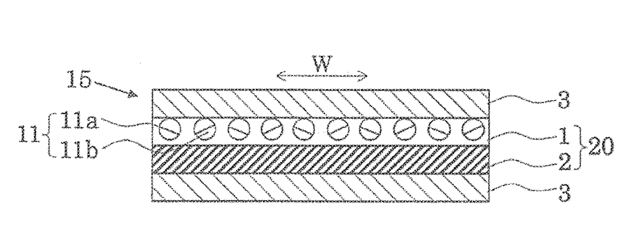
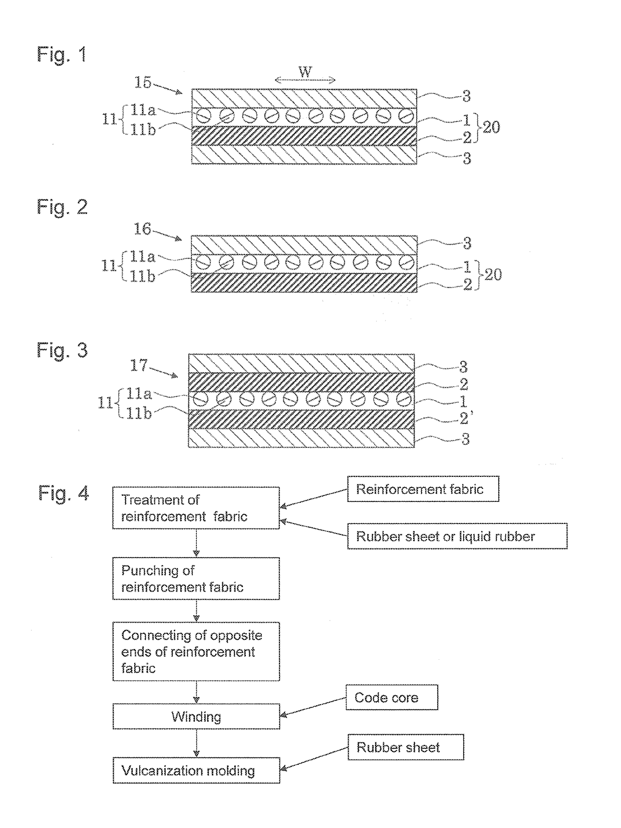
[0081]After sticking a nitrile rubber sheet with a thickness of 0.4 mm to a polyester canvas (reinforcement fabric) (refer to FIG. 5(a)), this was subjected to punching into a sawtooth shape, thereby separately forming convex parts and concave parts (refer to FIG. 5(b)). The convex parts were respectively disposed inside the concave parts and pressed at 100° C. (refer to FIG. 5(c)) into an endless canvas connected with each other through a finger joint shape with a width W of 15 mm and a length L of 70 mm as shown in FIG. 6.

[0082]Subsequently, the endless canvas was wound around the driver pulley 7a and the driven pulley 7b of the cord winding apparatus 7 as shown in FIG. 9. A twisted yarn obtained by uniformly arranging polyamide 46 of 470 dtex and then twisting up to 5600 dtex was used as a cord core. The cord core was spirally buried in the nitrile rubber sheet in the endless canvas while controlling the tension of the cord core by the tension control apparatus. Thereafter, a pol...

example 2

[0084]An endless flat belt having the structure shown in FIG. 3 and having a thickness of 3.2 mm and a circumferential length of 1500 mm was obtained in the same manner as in Example 1, except that polyamide 66 fabric of 5600 dtex was used as a cord core.

example 3

[0085]An endless flat belt having the structure shown in FIG. 3 and having a thickness of 3.2 mm and a circumferential length of 1500 mm was obtained in the same manner as in Example 2, except that opposite ends of a polyester canvas (reinforcement fabric) were sewn together in abutment against each other as shown in FIG. 8.


PUM

PropertyMeasurementUnit
thicknessaaaaaaaaaa
circumferential lengthaaaaaaaaaa
lengthaaaaaaaaaa

Abstract

An endless flat belt includes an inner rubber layer 1, a cord core 11 buried in the inner rubber layer 1 and spirally wound at a predetermined pitch in a width direction of the belt, and a reinforcement fabric 2 stuck to the inner rubber layer 1. The cord core comprises polyamide fiber. Opposite ends of the reinforcement fabric 2 are connected with each other into an endless form by adhesion or sewing. A surface rubber layer 3 is stuck to a surface of the reinforcement fabric 2 which is opposite a surface thereof stuck to the inner rubber layer 1.

Description

TECHNICAL FIELD[0001]The present invention relates to an endless flat belt used for the purposes of twist travel, such as a paper tube winding belt, and to a method for manufacturing the endless flat belt.BACKGROUND ART[0002]A flat belt conventionally used as a high-speed transmission belt is generally made into an endless belt by processing opposite ends of a band-shaped belt having a polyamide film as a core body into a joint shape, such as a skiver joint and a finger joint, followed by integrally adhering with an adhesive or thermal adhesion.[0003]However, because the adhesive usually has poor flexibility, the belt may be partially hardened at a joint part and stress concentration is apt to occur at the hardened portion, and consequently the durability, particularly bending resistance of the belt is apt to deteriorate. Cracks can occur at the joint part in a short period of time. In some cases, the belt can be broken.[0004]When manufacturing a paper tube, the paper tube is manufa...

Claims


Application Information

Patent Timeline
Patent Type & Authority Applications(United States)
IPC IPC(8): F16G1/10B32B25/02B32B25/10B29D29/00
CPCF16G1/10B29D29/00B32B25/02B32B2433/04B29K2277/00B32B2377/00B32B25/10F16G1/08Y10T428/1362
Inventor OKAMURA, HARUHIDEKONISHI, YOSHIHIROONO, MITSUAKINAKAI, NAOMICHIKAI, NAOKI
Owner NITTA CORP
Why Eureka
Try Eureka