
Imaging Light Guide With Reflective Turning Array

Active Publication Date: 2017-03-16
VUZIX
View PDF4 Cites 73 Cited by
  • Summary
  • Abstract
  • Description
  • Claims
  • Application Information

AI Technical Summary

Benefits of technology

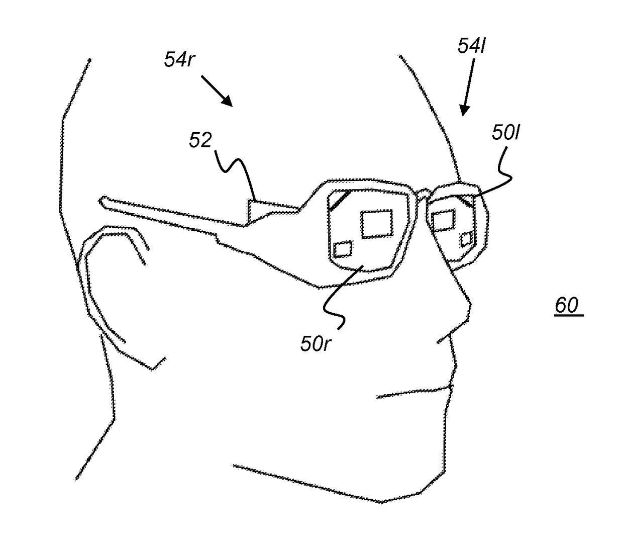
The present patent discusses advancements in image presentation within compact head-mounted displays. The invention provides a wearable display with an imaging light guide that offers an enlarged pupil size for presenting high resolution wide field of view (FOV) content to the viewer. This arrangement increases optical efficiency, brightness, and allows for more compact HMD and related display design options. It also offers image rotation and reversal, which is not possible with fully diffractive solutions. Overall, the invention improves image quality and provides a more immersive viewing experience for users.

Problems solved by technology

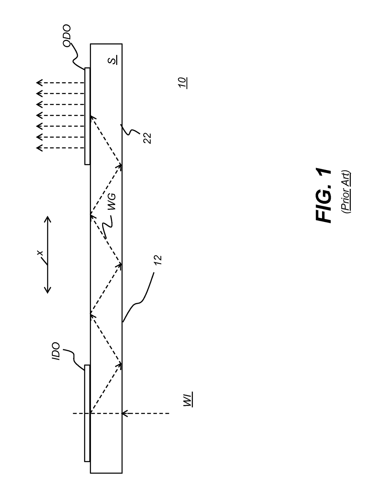
Although conventional imaging light guide arrangements have provided significant reductions in bulk, weight, and overall cost of near-eye display optics, overall efficiency of the gratings is often limited by optical losses occurring at each grating interface.
Further, if such a system did introduce rotation to the virtual image, it would do so non-uniformly across different field angles and wavelengths of light, thus causing unwanted distortions or aberrations in the resulting virtual image.
One-dimensional (1-D) pupil-expansion guides of the type Amitai describes, however, have proved to be costly and difficult to fabricate.
Extending this concept to 2-D beam expansion, using an array of mirrors oriented at a second set of angles, greatly complicates fabrication tasks that are already formidable and introduces alignment requirements that would be extremely difficult to satisfy.
However, if a turning grating were used to redirect light that has been input using a mirror or a prism, this would produce unwanted effects in the resultant virtual image.
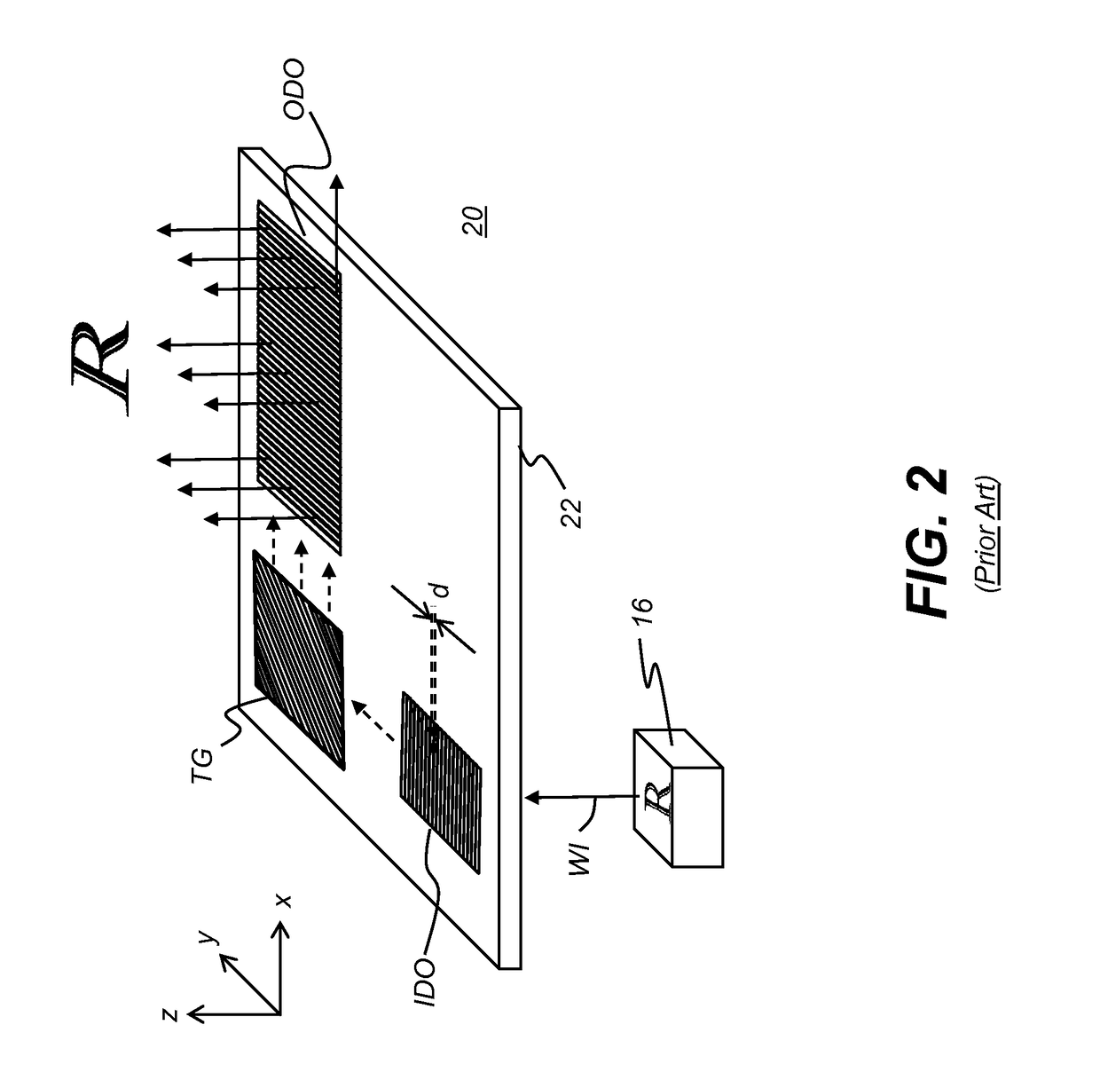
As one consideration, with any type of reflective surface used in imaging, there can be unwanted reversal / rotation of the in-coupled light.

Method used


Image

  • Imaging Light Guide With Reflective Turning Array
  • Imaging Light Guide With Reflective Turning Array
  • Imaging Light Guide With Reflective Turning Array

Examples


Embodiment Construction

[0029]The present description is directed in particular to elements forming part of, or cooperating more directly with, apparatus in accordance with the invention. It is to be understood that elements not specifically shown or described may take various forms well known to those skilled in the art.

[0030]Where they are used herein, the terms “first”, “second”, and so on, do not necessarily denote any ordinal, sequential, or priority relation, but are simply used to more clearly distinguish one element or set of elements from another, unless specified otherwise.

[0031]In the context of the present disclosure, the terms “viewer”, “operator”, “observer”, and “user” are considered to be equivalent and refer to the person who wears the HMD viewing device.

[0032]As used herein, the term “energizable” relates to a device or set of components that perform an indicated function upon receiving power and, optionally, upon receiving an enabling signal.

[0033]The term “set”, as used herein, refers t...


PUM


Abstract

An imaging light guide has a waveguide and an in-coupling diffractive optic formed on the waveguide and disposed to direct image-bearing light beams into the waveguide. An array of two or more at least partially reflective surfaces are oriented in parallel and disposed to expand the image-bearing light beams from the in-coupling diffractive optic in a first dimension and to direct the expanded image-bearing light beams toward an out-coupling diffractive optic. The out-coupling diffractive optic is formed on the waveguide and disposed to expand the image-bearing light beams in a second dimension orthogonal to the first dimension and to direct the image-bearing light beams toward a viewer eyebox.

Description

TECHNICAL FIELD[0001]This invention generally relates to electronic displays and more particularly relates to head-mounted (near-eye) displays that use imaging light guides to convey image-bearing light to a viewer.BACKGROUND OF THE INVENTION[0002]Head-Mounted Displays (HMDs) are being developed for a range of diverse uses, including military, commercial, industrial, fire-fighting, and entertainment applications. For many of these applications, there is particular value in forming a virtual image that can be visually superimposed over the real-world image that lies in the field of view of the HMD user. Optical imaging light guides convey image-bearing light to a viewer in a narrow space for directing the virtual image to the viewer's pupil and enabling this superposition function.[0003]In such conventional imaging light guides, collimated, relatively angularly encoded light beams from an image source are coupled into a planar waveguide by an input coupling such as an in-coupling dif...

Claims


Application Information

Patent Timeline
IPC IPC(8): G02B27/01G02B27/22G02B5/09G02B27/14H04N13/04G02B27/42
CPCG02B27/0172H04N13/044G02B27/4205G02B27/4272G02B2027/0123G02B27/141G02B27/2235G02B2027/0134G02B5/09G02B27/0081G02B6/0016G02B6/0026G02B6/0028G02B6/0038G02B6/006H04N13/344G02B30/34G02B6/00G02B30/35
Inventor SCHULTZ, ROBERT J.TRAVERS, PAUL J.
Owner VUZIX
Learn More