Formation and repair of oxide dispersion strengthened alloys by alloy melting with oxide injection

a technology of oxide dispersion and alloy, which is applied in the field of metal component fabrication and repair, can solve the problems of uneconomical processing, significant loss of strength, and difficult weld and repair of ods alloys, especially superalloys,

Active Publication Date: 2017-03-23
SIEMENS ENERGY INC
View PDF7 Cites 3 Cited by
  • Summary
  • Abstract
  • Description
  • Claims
  • Application Information

AI Technical Summary

Problems solved by technology

ODS alloys, especially superalloys, are very difficult to weld and repair by conventional techniques (e.g., gas tungsten arc welding, laser welding, electron beam welding, etc.).
Such fusion welding causes significant loss of strength.
The alloys are furthermore difficult and uneconomical to process by less traditional processes such as friction welding.
However, ODS processing is slow, expensive and provides limited control of part geometry.
In addition, joining or repair of ODS parts is very difficult.
Conventional arc and energy beam processes cause the fine oxide particles to segregate or coalesce, which degrades the result.
Nickel based ODS superalloys are especially difficult to cold work and recrystallize.
Additional challenges associated with ODS alloys involve general shaping and joining of these materials.
Shaping and joining techniques which preserve the microstructure and intrinsic strength of ODS alloys are severely limited, which often curtails their ability to be incorporated into high-temperature, load-bearing structures.
For example, excessive heating of ODS alloys can cause the oxide to coalesce, leading to agglomeration such that the oxide dispersoids may no longer be effective in resisting slip at the grain boundaries.
Melting of ODS alloys also results in “slagging off” of the oxide dispersoids reducing their strengthening ability.
Since most ODS alloys derive their strength from an elongated grain structure, such disruption of the grain structure reduces strength.

Method used


Image

  • Formation and repair of oxide dispersion strengthened alloys by alloy melting with oxide injection
  • Formation and repair of oxide dispersion strengthened alloys by alloy melting with oxide injection
  • Formation and repair of oxide dispersion strengthened alloys by alloy melting with oxide injection

Examples


Embodiment Construction

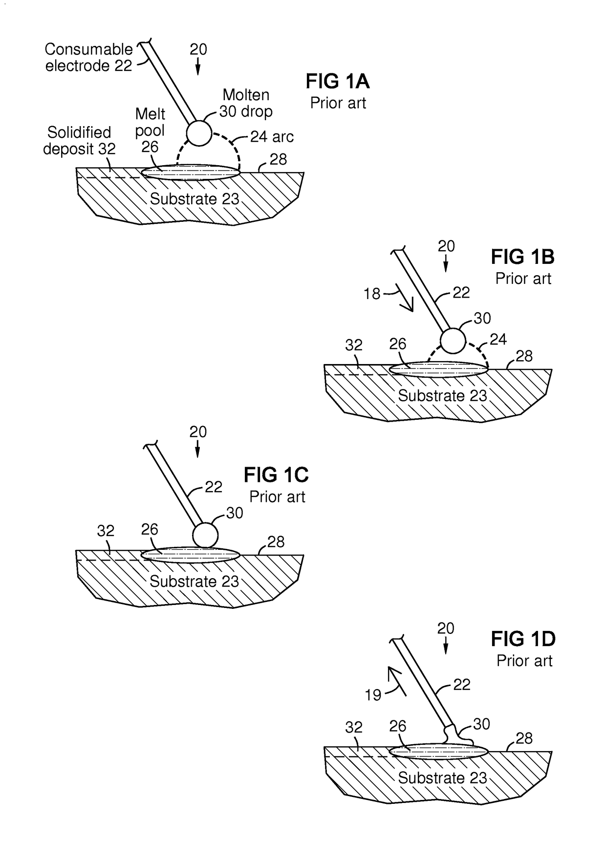
[0014]FIG. 1A-1D illustrate basic apparatus and steps in a known cold metal transfer process 20. In FIG. 1A, a consumable electrode 22 approaches an electrically conductive substrate 23, establishing an arc 24 that melts a melt pool 26 on a surface 28 of the substrate and creates a melt drop 30 of alloy filler material on the electrode tip. The melt pool solidifies into a deposit 32 on the substrate. In FIG. 1B the consumable electrode 22 is advanced 18 toward the melt pool. In FIG. 1C the melt drop 30 touches the melt pool, extinguishing the arc. Electrical current is prevented from spiking during the short circuit by a controller (not shown). In FIG. 1D the melt drop 30 adheres to the melt pool, and the electrode 22 is retracted 19. This pulls the drop 30 off of the electrode into the melt pool by surface tension, thus adding the drop as alloy filler material to the melt pool. This technology minimizes spatter and excess heating compared to other arc welding techniques, while prov...


PUM

PropertyMeasurementUnit
first energyaaaaaaaaaa
melting pointaaaaaaaaaa
energyaaaaaaaaaa

Abstract

Melting energy exemplified by an arc (24) is delivered to a metal alloy material (22, 23), forming a melt pool (26). A metal oxide material (34) is delivered (33) to the melt pool and dispersed therein. The melting energy and oxide deliveries are controlled (44) to melt the alloy material, but not to melt at least most of the metal oxide material. The deliveries may be controlled so that the melting energy does not intercept the metal oxide delivery. The melting energy may be controlled to create a temperature of the melt pool that does not reach the melting point of the metal oxide. Deliveries of the melting energy and the oxide may alternate so they do not overlap in time. A cold metal transfer apparatus (22) and process (18, 19, 20) may be used for example in combination with an oxide particle pulse delivery device (42, 46).

Description

FIELD OF THE INVENTION[0001]This invention relates generally to the field of metal-component fabrication and repair, and more particularly to the formation of oxide dispersion strengthened (ODS) alloys.BACKGROUND OF THE INVENTION[0002]Oxide dispersion strengthened (ODS) alloys possess superior properties for high temperature applications; especially ODS alloys formed of superalloy materials. ODS alloys are distinguished from conventional alloys by the presence of dispersoids of fine particles and by an elongated grain shape which generally develops during a recrystallization heat treatment and / or hot and cold working. This particular grain structure enhances the high temperature deformation characteristics of ODS alloys by inhibiting the accumulation of inter-granular damage. As result of this and other properties, components fabricated from ODS alloys exhibit improved high-temperature creep strength and improved oxidation resistance as compared to conventional alloys.[0003]The term...

Claims


Application Information

Patent Timeline
Patent Type & Authority Applications(United States)
IPC IPC(8): B23K9/04B23K9/23B23K9/12B23K9/32B23K9/00B23K9/09
CPCB23K9/04B23K9/0026B23K9/091B23K9/12B23K2203/08B23K9/23B23K2203/18B23K2203/50B23K9/324C23C26/02B23K2103/166B23K2103/50B23K2103/08B23K2103/18
Inventor BRUCK, GERALD J.
Owner SIEMENS ENERGY INC
Why Eureka
Try Eureka