Spot welding method

a welding method and welding plate technology, applied in welding/soldering/cutting articles, manufacturing tools, transportation and packaging, etc., can solve the problems of insufficient formation of the splint (weld metal), low pressing force at the time of the first stage of welding, and inability to obtain the desired joint strength

Active Publication Date: 2017-03-23
NIPPON STEEL CORP
View PDF5 Cites 5 Cited by
  • Summary
  • Abstract
  • Description
  • Claims
  • Application Information

AI Technical Summary

Benefits of technology

[0047]According to the present invention, the problem is to obtain a suitable welded joint in spot welding of a plurality of superposed steel sheets even when there is a gap between the steel sheets (sheet gap) and further the sheet thickness ratio (sum of sheet thicknesses of superposed steel sheets / sheet thickness of thinnest steel sheet) is large. In particular, the object is application to an automobile member. It is possible to provide spot welding able to be applied even when arranging a relatively thin steel sheet at the outermost layer (electrode-most side).In particular, this effect is exhibited in spot welding of a plurality of steel sheets including a high strength steel sheet and further having the steel sheet with the thinnest sheet thickness arranged at the outermost side.

Problems solved by technology

At this time, sometimes the nugget (weld metal) is not sufficiently formed at the interface between the thin sheet and thick sheet.
However, with the method of PLT 1, the pressing force at the time of the first stage of welding is low, so there is a sheet gap between the steel sheets (gap between steel sheets).
Further, if the sheet thickness ratio (=total sheet thickness (mm) / thinnest sheet thickness (mm)) is large, sometimes a nugget is not sufficiently formed at the interface of a thin sheet and thick sheet and the desired joint strength cannot be obtained.
In the method of PLT 2, the pressing force is increased in the second step, but if there is a sheet gap and the sheet thickness ratio is high, it is difficult to secure the desired nugget size.
In the method of PLT 3, to enlarge the nugget, at the third step, a pressing force larger than the pressing force of the first step is imparted, but in the same way as the method of PLT 2, if there is a sheet gap and the sheet thickness ratio is high, it is difficult to secure the desired nugget size.
In this way, when superposing a plurality of steel sheets with a sheet gap and a high sheet thickness ratio, it is difficult to sufficiently melt the contact interface of a thin steel sheet and a thick steel sheet and sufficiently form the nugget and sometimes the desired joint strength cannot be obtained.

Method used


Image

  • Spot welding method
  • Spot welding method
  • Spot welding method

Examples


example 1

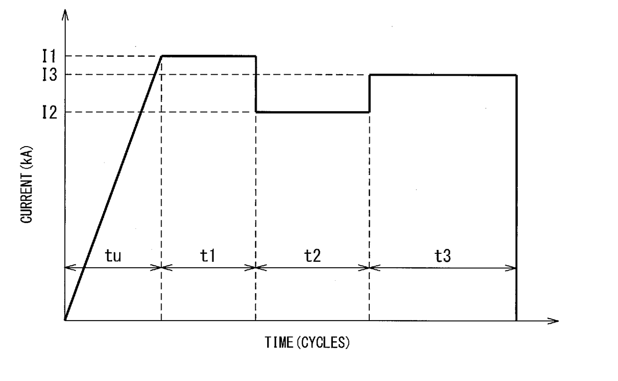
[0107]Using the two types of sets of sheets shown in Table 1, spot welding was performed. The steel sheets were all galvannealed steel sheets. The amount of deposition per side was 45 g / m2. The spot welding conditions are shown in Table 2. For the welding power source, a single phase alternating current was used.

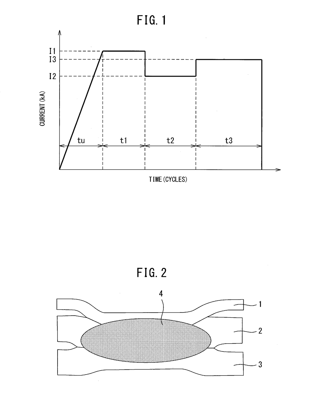
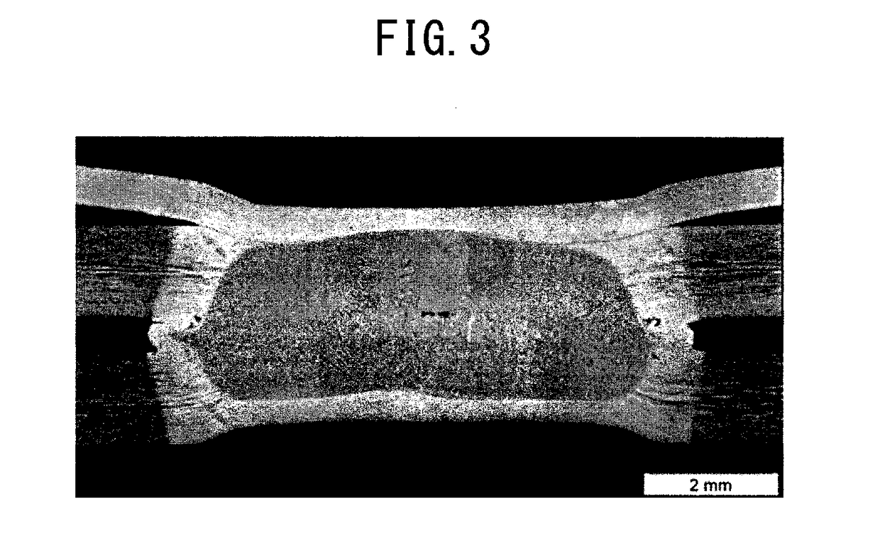
[0108]For the electrodes, a Cr—Cu DR type having a nominal size of 16 mm, a tip diameter of 6 mm, and a tip R of 40 mm was used. The electrode holding time after three stages of conduction was made 5 cycles in all cases. After welding, the set of sheets was cut along a line passing through the center of the spot welding. The cut surface was polished and etched, then the size of the nugget was measured by an optical microscope. The measurement results are shown in Table 3 together with the occurrence of expulsion. A nugget of (Nugget size between Steel Sheets 1 and 2) ≧4×√ (sheet thickness of Steel Sheet 1) was judged as passing.

example 2

[0109]Under the same conditions as Example 1, spot welding was performed by the conduction pattern and pressing force pattern of FIG. 5. The spot welding conditions and results of evaluation are shown in Table 4. For the welding power source, single-phase alternating current was used.

[0110]As a result, no expulsion occurred and a good nugget was formed. Note that, a nugget of a nugget size between steel sheets of ≧4×√ (sheet thickness of Steel Sheet 1 (thinnest steel sheet)) was judged as passing. Below, the same criteria were used for judgment in Examples 3, 4, and 5 as well.

example 3

[0111]Under the same conditions as Example 1, spot welding was performed by the conduction pattern and pressing force pattern of FIG. 6. The spot welding conditions and results of evaluation are shown in Table 5. For the welding power source, single-phase alternating current was used.

[0112]As a result, no expulsion occurred and a good nugget was formed.


PUM

PropertyMeasurementUnit
thicknessaaaaaaaaaa
currentaaaaaaaaaa
thicknessaaaaaaaaaa

Abstract

The spot welding method of the present invention has steps of preliminary conduction, first conduction, second conduction, and third conduction:Preliminary conduction: Conduction method aimed at improving closeness of contact surfaces of steel sheets and reducing sheet gaps by gradually increasing the welding current (for example, upslope conduction). If rapidly applying current, current would be locally carried and that part would melt resulting in expulsion, so this is a conduction method gradually running current (for example upslope conduction) to avoid local heating.First conduction: Conduction method running a constant welding current and using the heat generated by the electrical contact resistance between steel sheets to cause the formation of a nugget when preliminary conduction results in close contact surfaces between the steel sheets.Second conduction: Conduction method making the current lower than the first conduction to suppress inside expulsion while making the nugget grow in the diametrical direction.Third conduction: Conduction method making the current higher than the second conduction and making the nugget grow not only in the diametrical direction, but also mainly in the sheet thickness direction when the nugget size becomes a certain extent of size at the second conduction step.

Description

TECHNICAL FIELD[0001]The present invention relates to a spot welding method for joining a plurality of superposed steel sheets.BACKGROUND ART[0002]In the past, the main welding method in the automobile field has been spot welding. Steel sheets have been joined by spot welding to assemble the chassis and produce parts.[0003]For example, in an automobile chassis, mild steel sheet excellent in shapeability and paintability has been used for outside panel parts with high design property. High strength steel sheet has been used for frame parts for ensuring inside strength and rigidity. Usually, mild steel sheet with a relatively thin sheet thickness and high strength steel sheet with a relatively thick sheet thickness are applied.[0004]Therefore, portions arise where thin mild steel sheet and thick high strength steel sheet are joined by spot welding. At this time, sometimes the nugget (weld metal) is not sufficiently formed at the interface between the thin sheet and thick sheet.[0005]P...

Claims


Application Information

Patent Timeline
Patent Type & Authority Applications(United States)
IPC IPC(8): B23K11/24B23K11/16B23K11/11
CPCB23K11/24B23K2201/006B23K11/16B23K11/11B23K11/115B23K2101/18B23K2103/04B23K2101/006B23K11/241B23K11/34
Inventor FURUSAKO, SEIJIMIYAZAKI, YASUNOBUNISHIBATA, HITOMITAKAHASHI, YASUO
Owner NIPPON STEEL CORP
Why Eureka
Try Eureka