
Heating device

a technology of heating device and heat sink, which is applied in the direction of heat pumps, heating types, and ways, etc., can solve the problems of increasing outcompetence, wasting energy, and wasting energy, and achieves energy-saving thawing devices, high energy and cost consciousness, and fast and further heating/melting.

Active Publication Date: 2017-03-23
EXPERTUS KEMITEKNIK
View PDF1 Cites 0 Cited by
  • Summary
  • Abstract
  • Description
  • Claims
  • Application Information

AI Technical Summary

Benefits of technology

The present invention provides a heating device and method for thawing ground that is energy efficient. The use of low-temperature heat from brine circuit and high-temperature heat from heat pump with the aid of commonly available property heat pumps helps to build affordable thawing devices. The device is well-suited for mild weather conditions and can quickly thaw ground. Afterward, heat pump energy can be supplied for further heating and melting. The device improves speed when insulation is arranged under the coils. However, a certain depth of the device is needed to reduce the risk of freezing during quick weather changes when the thawing device is turned off.

Problems solved by technology

Ground placed electrical coils have commonly been used but are increasingly being outcompeted by the cheap energy provided by geothermal heat pumps, wherein you arrange thaw coils with anti-freeze liquid instead of electrical coils.
A drawback of the known art is that thawing is energy consuming.
If, at the same time, the weather is cold, much energy is lost to the surroundings.

Method used


Image

  • Heating device
  • Heating device
  • Heating device

Examples


case 1

wing Function is Used

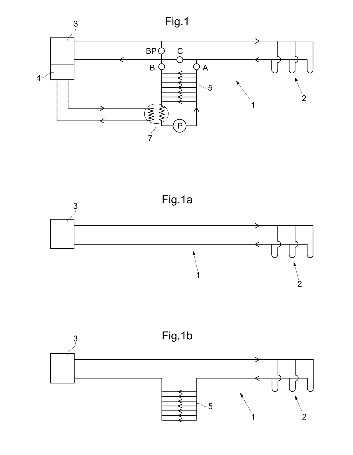
[0072]The heat pump 3, e.g. the geothermal heat pump, can operate, see FIG. 3a. This first operation mode is essentially identical to the first operation mode of the first embodiment described above with reference to FIG. 1a.

case 2

g Solely Using Brine Solution

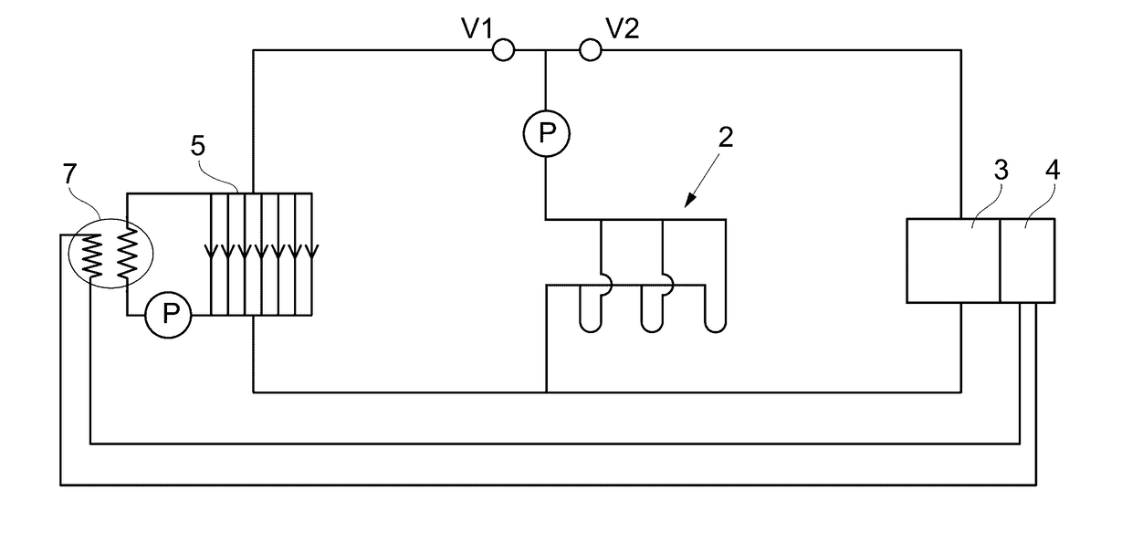
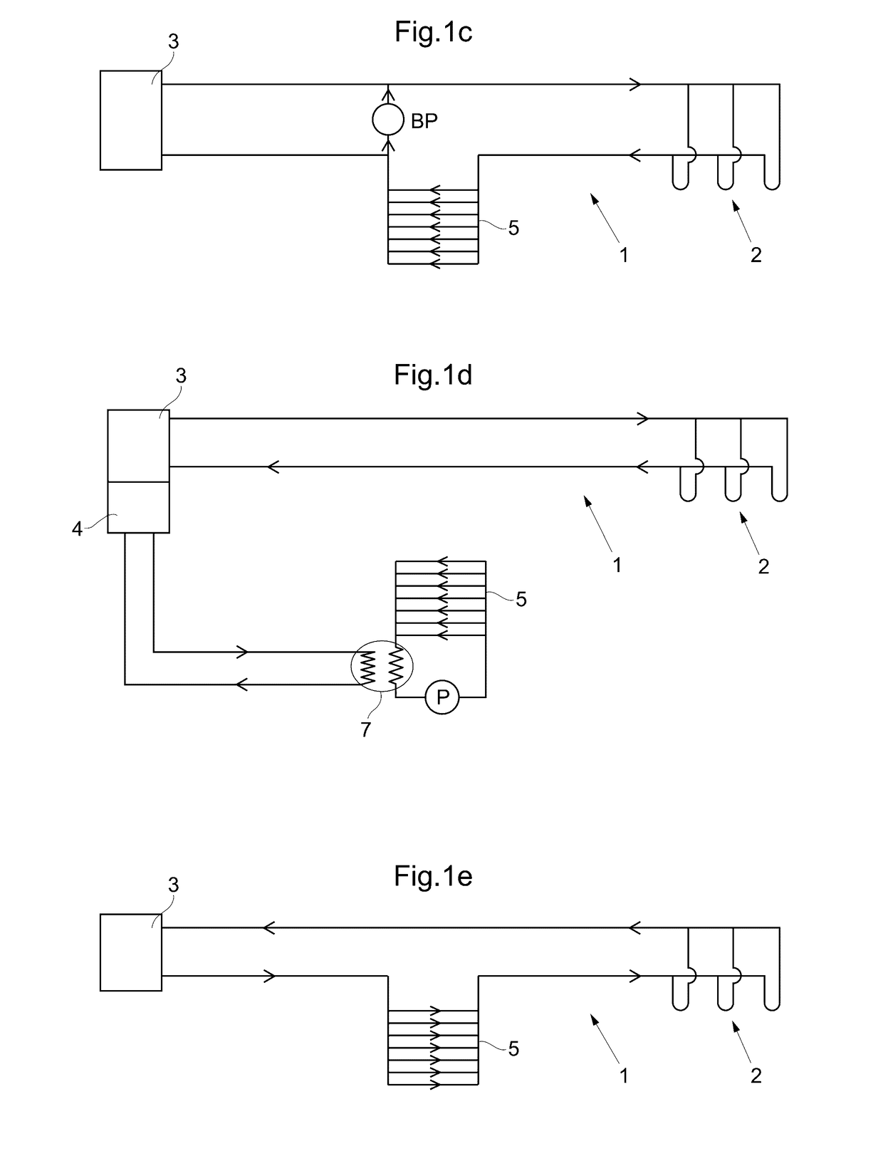
[0073]In the second operation mode, shown in FIG. 3b, the heat pump 3, e.g. the geothermal heat pump, operates or the circulation pump in the heat pump 3 is mechanically operated, i.e. forced controlled during non-operation by the heat pump but when its circulation pump has to operate to provide circulation through the thaw coils. In this operation mode, the energy well 2 and the thaw coils 5 are interconnected.

[0074]In the third operation mode, shown in FIG. 3c, the heat pump 3 is arranged such that circulation thorough the energy well 2 is achieved for heating the building. Also, the energy well 2 provides energy for heating the thaw coils 5 by circulating fluid by means of the pump P through the circuit formed by the energy well 2 and the thaw coils 5.

case 3

g with Heat Pump Energy

[0075]In the fourth operation mode, shown in FIG. 3d, the heat pump 3, e.g. the geothermal heat pump, operates. The energy extraction device 4 provides the heat to the thaw coils 5 via the heat exchanger 7.

[0076]Preferred embodiments of a heating device 1 according to the invention have been described. However, the person skilled in the art realizes that these can be varied within the scope of the appended claims without departing from the inventive idea.

[0077]All the described alternative embodiments above or parts of an embodiment can be freely combined without departing from the inventive idea as long as the combination is not contradictory. Thus, the circuits of the first, second and / or third embodiments can be combined into one system by the use of appropriate conduits and connections.


PUM


Abstract

A heating device (1) comprising: an energy well (2), a heat pump (3) which is adapted to take up and transfer heat from the energy well (2) by the aid of a line from the energy well to the heat pump (3) for transport of anti-freeze liquid, a heat extraction device (4) connected to a heat pump (3) which selectively can be brought into a connected and a disconnected position, thaw coils (5) for thawing ground surrounding the thaw coils (5), in which the anti-freeze liquid is transportable, which thaw coils (5) selectively can be connected and disconnected to the line from the energy well to the heat pump (3), a heat exchanger (7) connected to the heat extraction device (4) adapted to selectively transfer heat to the thaw coils (5) by the aid of the heat extraction device (4), a control system (6) which is adapted for controlling the heating device (1) whereby low temperature heat from the energy well (2) alternatively high temperature heat from the heat pump (3) and the heat extraction device (4) selectively can be used for pre-heating, thawing, or maintenance heating ground surrounding the thaw coils (5).

Description

TECHNICAL FIELD[0001]The present invention relates generally to a heating device and a method for thawing ground.BACKGROUND ART[0002]There is a need to thaw ground in an energy efficient manner to reduce the risk of slipping, on airfields, garage and other driveways / slopes, approaches, roads, etc. Ground placed electrical coils have commonly been used but are increasingly being outcompeted by the cheap energy provided by geothermal heat pumps, wherein you arrange thaw coils with anti-freeze liquid instead of electrical coils.[0003]A drawback of the known art is that thawing is energy consuming. The melting heat for ice is high (80 cal / gram) and frozen ground, especially at a high water content therefore requires also much energy for thawing, in addition to the ice and snow that may lay on the ground surface. If, at the same time, the weather is cold, much energy is lost to the surroundings. This is reinforced by wind and a relatively high humidity.SUMMARY OF INVENTION[0004]An object...

Claims


Application Information

Patent Timeline
IPC IPC(8): E01C11/26F24J3/08
CPCF24J3/086E01C11/26E01C11/24F24D3/18F25B30/06F24D2200/11F24D2200/14Y02B10/20F25B25/005F25B2339/047F24T10/10Y02B30/12E01C13/083E01C11/245Y02B10/40Y02B10/70Y02E10/10
Inventor SJOLEN, LENNART
Owner EXPERTUS KEMITEKNIK
Learn More