Eureka AIR delivers breakthrough ideas for toughest innovation challenges, trusted by R&D personnel around the world.

Engine, Biomass Powder Energy Conversion and/or Generation System, Hybrid Engines Including the Same, and Methods of Making and Using the Same

a biomass powder and energy conversion technology, applied in the field of mechanical energy generation, can solve the problems of reducing the efficiency of the engine, heavy load of fuel and oxidizers in the conventional engine, etc., and achieve the effects of improving efficiency, improving the performance of the existing engine, and reducing fuel consumption

Inactive Publication Date: 2017-03-23
LEE BRENT
View PDF39 Cites 17 Cited by
  • Summary
  • Abstract
  • Description
  • Claims
  • Application Information

AI Technical Summary

Benefits of technology

The present invention is a new engine and system for energy conversion and generation using biomass powder. The engine is more efficient, has less wear and tear, and can use alternative fuels. The system can be used for power generation or mechanical drive applications. The engine is simpler and easier to manufacture and repair, and can contribute a relatively high proportion of thrust towards rotational torque. The technical effects of the invention include improved efficiency, reduced fuel consumption, and greater power generation.

Problems solved by technology

Existing technology that transforms biomass material for energy typically results in a liquid or a gaseous fuel, and is generally obtained through complex and expensive processes.
In addition, conventional engines carry a heavy load of fuel and oxidizers.
However, fuel and oxidizer must be stored in the rocket housing, and the weight of the fuel and oxidizer necessitates more fuel and oxidizer (e.g., to move the fuel and oxidizer), and decreases the efficiency of the engine.

Method used


Image

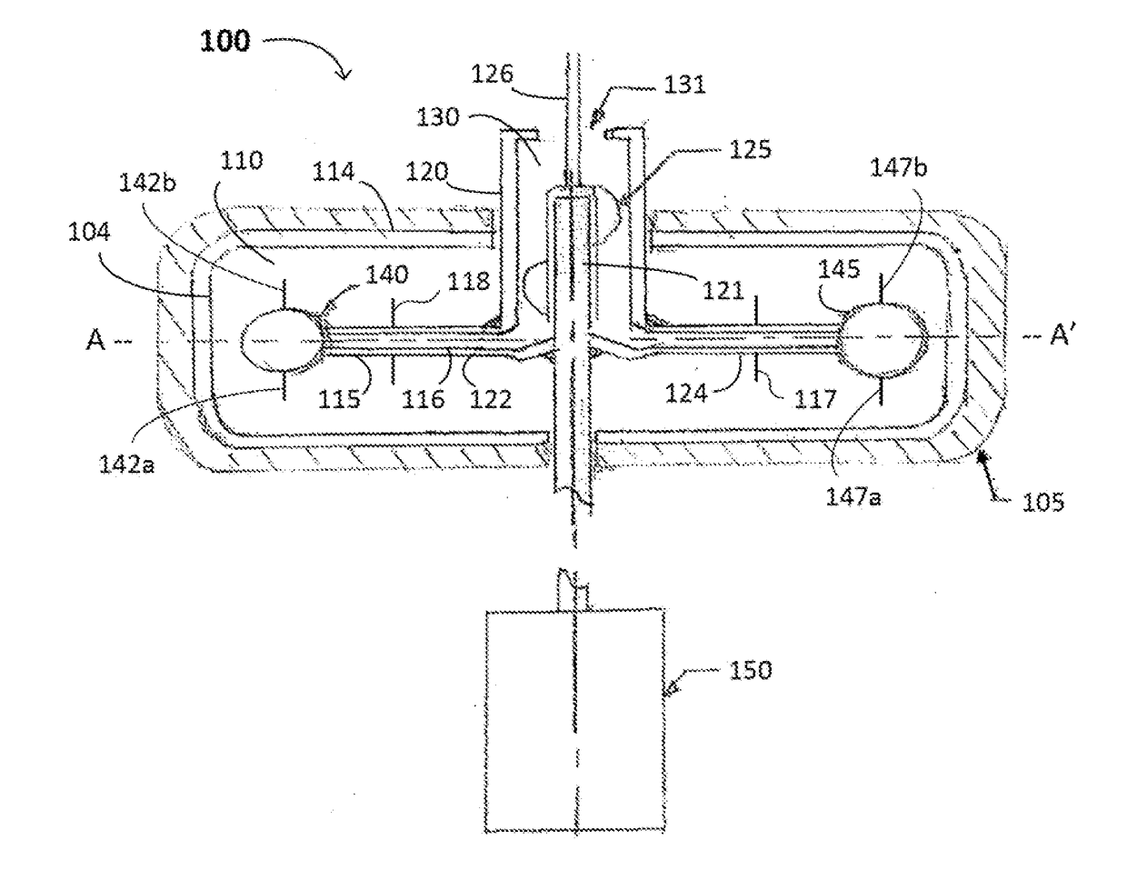
  • Engine, Biomass Powder Energy Conversion and/or Generation System, Hybrid Engines Including the Same, and Methods of Making and Using the Same
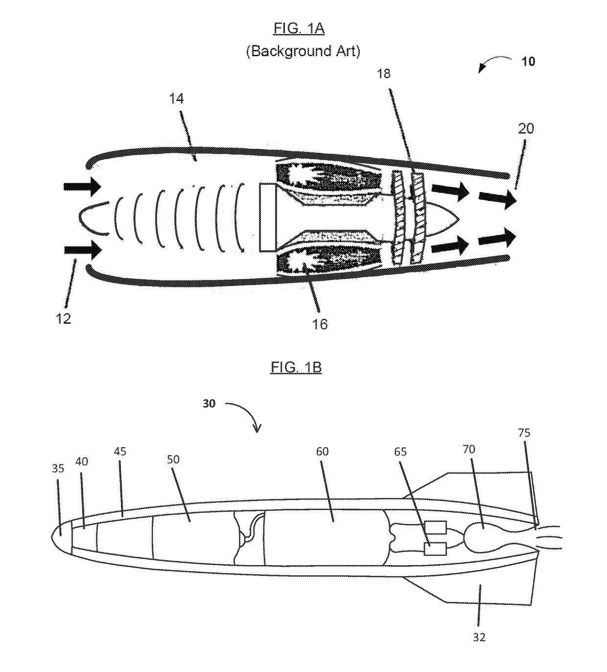
  • Engine, Biomass Powder Energy Conversion and/or Generation System, Hybrid Engines Including the Same, and Methods of Making and Using the Same
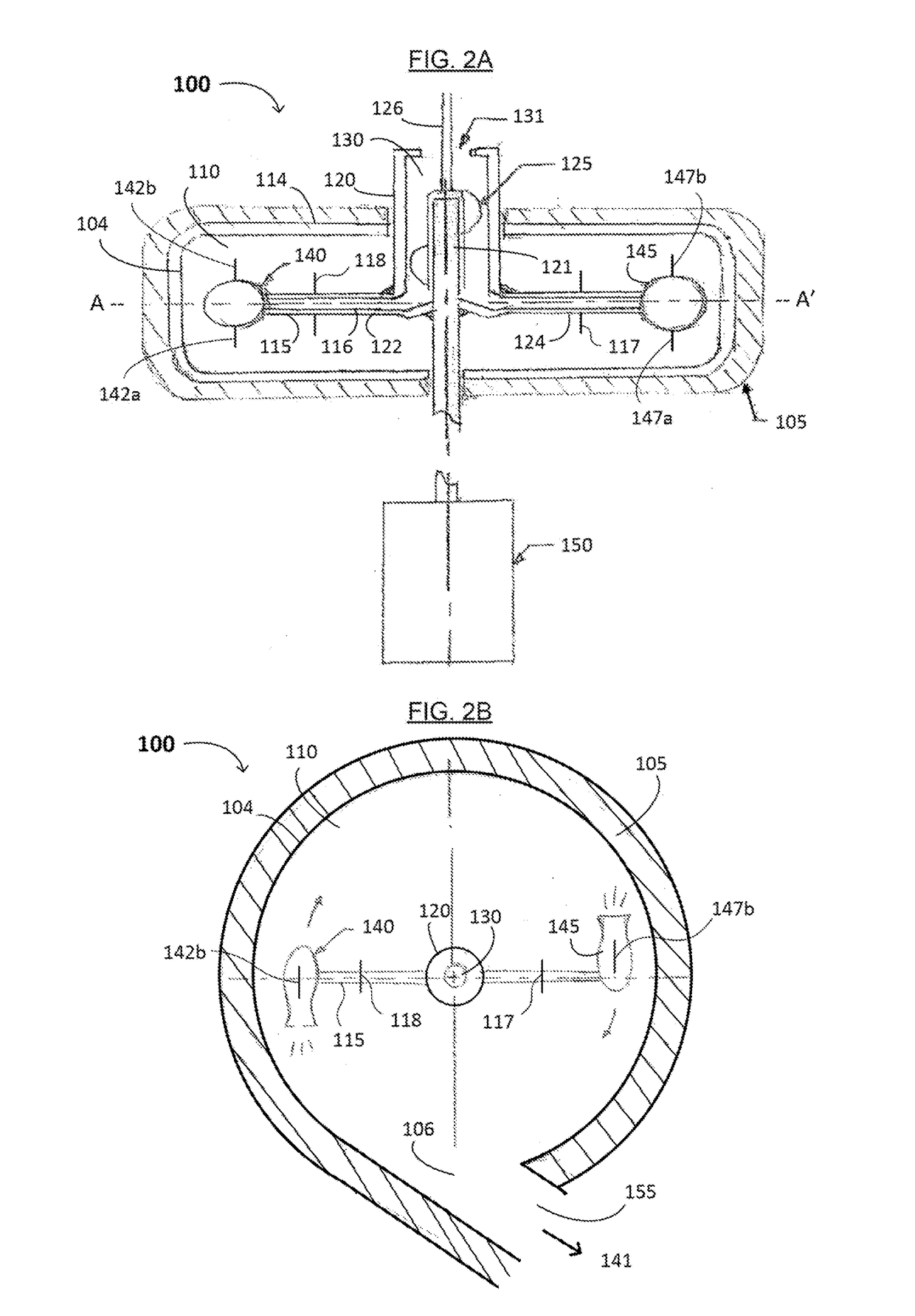
  • Engine, Biomass Powder Energy Conversion and/or Generation System, Hybrid Engines Including the Same, and Methods of Making and Using the Same

Examples


Embodiment Construction

[0041]Reference will now be made in detail to various embodiments of the invention, examples of which are illustrated in the accompanying drawings. While the invention will be described in conjunction with the following embodiments, it will be understood that the descriptions are not intended to limit the invention to these embodiments. On the contrary, the invention is intended to cover alternatives, modifications and equivalents that may be included within the spirit and scope of the invention. Furthermore, in the following detailed description, numerous specific details are set forth in order to provide a thorough understanding of the present invention. However, it will be readily apparent to one skilled in the art that the present invention may be practiced without these specific details. In other instances, well-known methods, procedures, components, and materials have not been described in detail so as not to unnecessarily obscure aspects of the present invention.

[0042]Thus, t...


PUM


Abstract

An engine, a biomass powder energy conversion and / or generation system, hybrid turbine engines, and methods of manufacturing and using the same are disclosed. The engine includes a housing having an inner wall and an outer wall, a central rotary shaft extending from the housing, at least one fuel and air supply channel having a first portion extending radially from the rotary shaft and a second portion in fluidic communication with first portion of the fuel and air supply channel, at least two propulsion vessels, each propulsion vessel connected to the at least one of the fuel and air supply channel and configured to burn or detonate the fuel and rotate around the central rotary shaft; and at least one exhaust duct extending from the housing.

Description

CROSS REFERENCE TO RELATED APPLICATION[0001]This application claims the benefit of U.S. Provisional Patent Application No. 61 / 967,872, filed on Mar. 28, 2014, 61 / 995,635, filed on Apr. 16, 2014, and 61 / 995,842, filed on Apr. 22, 2014, each of which is incorporated herein by reference as if fully set forth herein.FIELD OF THE INVENTION[0002]The present invention generally relates to the field of mechanical energy generation. More specifically, embodiments of the present invention pertain to a novel engine, a biomass powder energy conversion and / or generation system, hybrid engines including the same (e.g., hybrid turbine engines), and methods of manufacturing and using the same.DISCUSSION OF THE BACKGROUND[0003]Recently, developing alternative fuels to decrease the dependence of fossil fuel has become a national and worldwide concern. Existing technology that transforms biomass material for energy typically results in a liquid or a gaseous fuel, and is generally obtained through comp...

Claims


Application Information

Patent Timeline
Patent Type & Authority Applications(United States)
IPC IPC(8): F02C3/26F02C7/04F01D25/30F02C7/264F02K3/062F02C3/04F02C7/22
CPCF02C3/26F02C3/04F02C7/04F02C7/222F02C7/264F05D2220/75F01D25/30F05D2220/30F05D2240/35F05D2210/13F02K3/062F02C3/165Y02T50/60
Inventor LEE, BRENT
Owner LEE BRENT
Why Eureka
Eureka Blog
Learn More