Stress or accumulated damage monitoring system

a monitoring system and stress or accumulation technology, applied in the field of real-time stress and/or accumulation damage monitoring system, can solve the problems of limited use of monitoring system, affecting productivity and maintenance cost, and so as to minimize stress/cumulative damage of boom and stick, the effect of reducing the risk of catastrophic failur

Active Publication Date: 2017-03-30
TECH MINING
View PDF2 Cites 14 Cited by
  • Summary
  • Abstract
  • Description
  • Claims
  • Application Information

AI Technical Summary

Benefits of technology

[0021]The invention allows for the first time a real-time assessment of the parameter of most interest to the mine operator—how much is the current operation and operator practices damaging the equipment and affecting the productivity and maintenance cost?
[0022]In the context of the excavator and truck examples above, the detailed capabilities

Problems solved by technology

While useful, such relative information cannot advise on how close the equipment is to failure or how much damage is occurring through fatigue.
Without such information, the monitoring system is of limited use in assisting the mine operation and equipment operator in their goal in cost-efficiently maximizing production while minimizing damage to the equipment.
According to the current

Method used


Image

  • Stress or accumulated damage monitoring system
  • Stress or accumulated damage monitoring system
  • Stress or accumulated damage monitoring system

Examples


example 1

HITACHI EX3600 Excavator

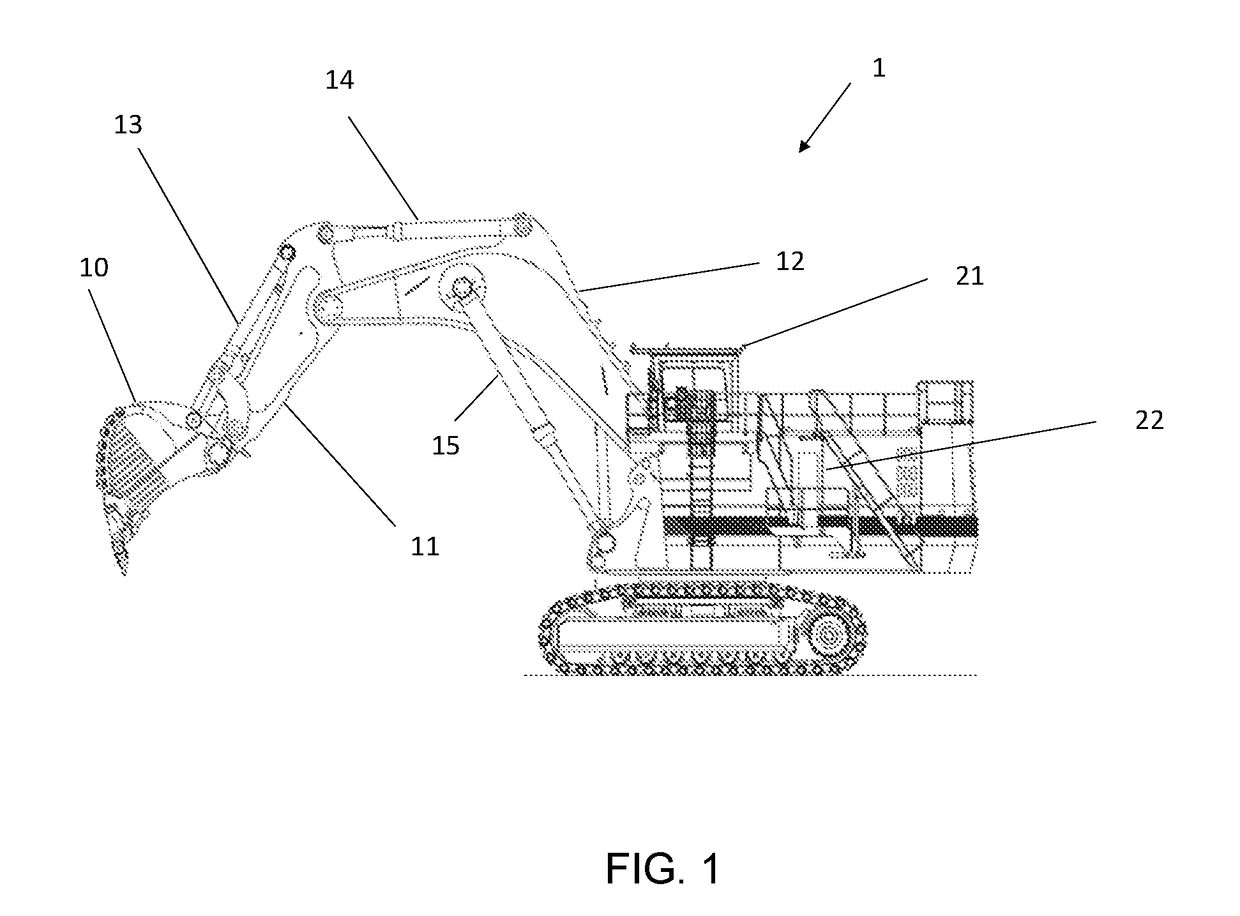
[0054]Referring first to FIG. 1, the embodiment to be described is applied to an HITACHI EX3600 excavator 1 comprising bucket 10, stick 11 and boom 12. Boom 12 is rotatably attached to the excavator body and is driven by hydraulic piston actuator 15. Stick 11 is rotatably attached to boom 12 and is driven by hydraulic piston actuator 14. Similarly, bucket 10 is rotatably attached to stick 11 and is driven by hydraulic piston actuator 13 (also referred to herein as a stick actuator). Excavator body has driver's cabin 21 atop engine room 22.

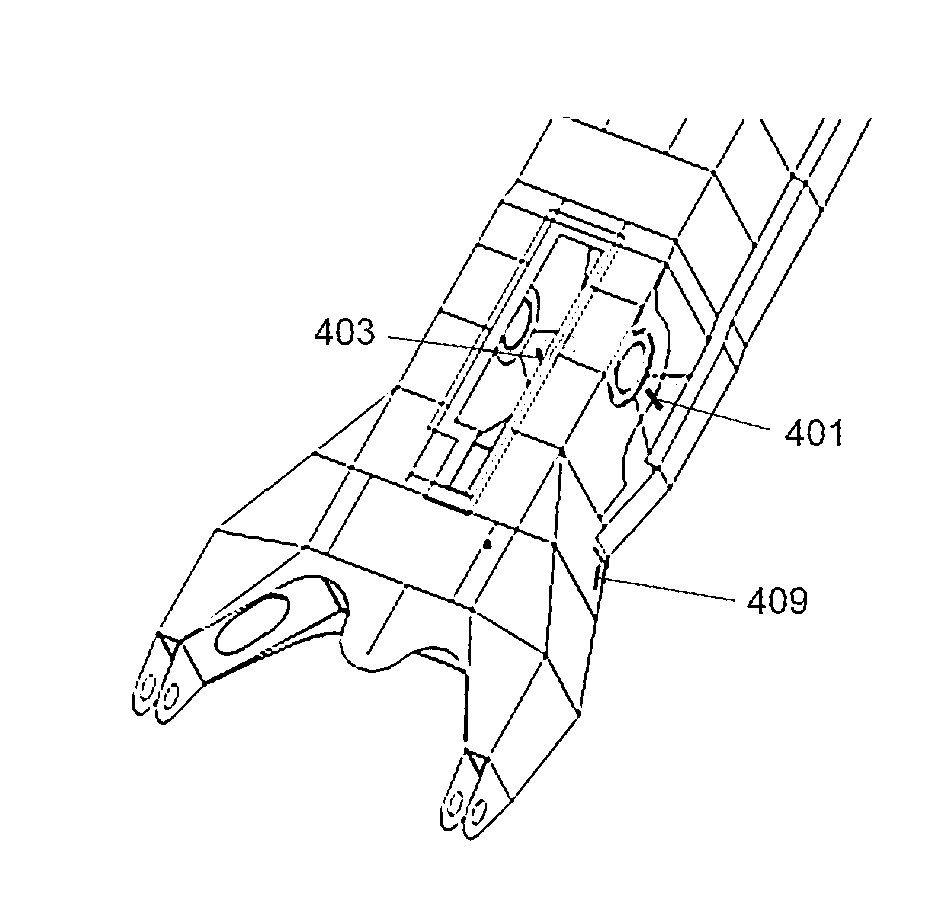
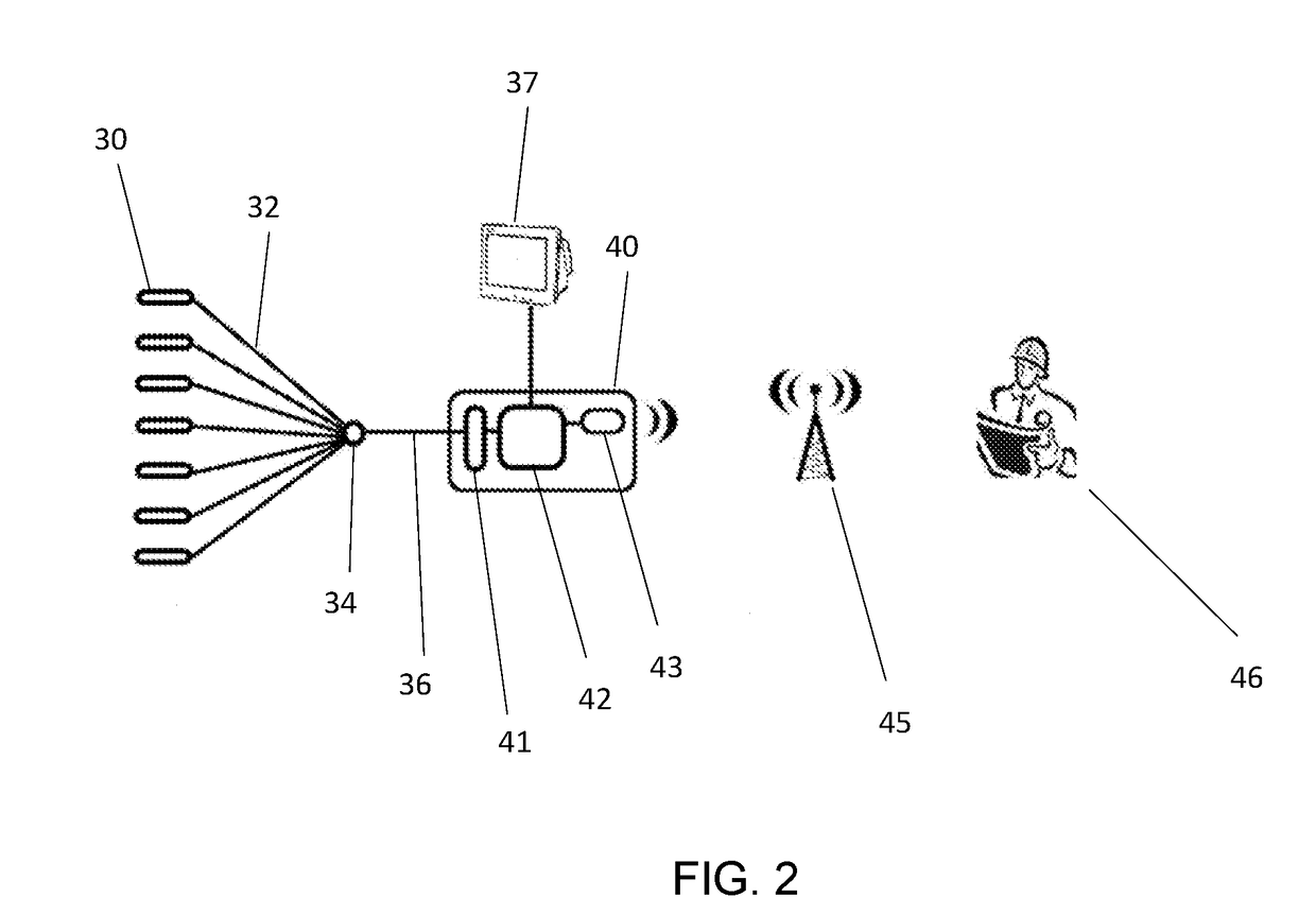
[0055]Referring also now to FIGS. 2 and 3, a plurality of sensors 30 are distributed over boom and stick, including piezoelectric strain gauges, pressure sensors and inclinometers. The strain gauges 52-60 are located at strain gauge locations determined by detailed analysis (described in more detail later) as the most critical locations on the boom and stick that can be used to accurately estimate the stress or cumulative da...

example 2

Trucks

[0091]Two embodiments applicable to a CATERPILLAR CAT793 C or D 240 tonne truck and a CAT 797 B or C 360 tonne truck will now be described together.

[0092]With currently available truck fatigue systems, the fatigue Life is based on measurements of all criteria (Racking+Pitching+Rolling) as measured from strut pressures, and producing a fatigue life prediction for the entire chassis, not for specific areas. In reality, the fatigue life will vary significantly from location to location, depending on the stress range, number stress cycles experienced and the fatigue category detail of the welded connection. The various locations on the chassis will also experience more or less damage due to the specific operating conditions such as rack, pitch, roll and bounce. Having one curve applied to all locations of the chassis can be extremely conservative or in some cases would be non-conservative.

[0093]Referring now to FIGS. 5a and 5b, a chassis of the CAT 793 C or D truck is shown in two...

example 3

Electric Rope Shovels

[0118]With electric rope shovels, a key goal of the monitoring system is typically to minimize the damage on the boom and dipper handle. However monitoring of the dipper handle is not possible because it slides within the boom saddle block. Hence it is extremely difficult to locate sensors on the handles. This difficulty is overcome by locating sensors on critical locations on the boom to derive the fatigue that the boom experiences and this can be used from the FEA modelling to infer damage occurring in the dipper handle. Lateral bending of the dipper handles during operations (swing with the dipper engaged in dirt) contribute significantly to the most common failure mode of the dipper handles.

[0119]As with the previous examples on excavators and trucks, the system applied to shovels can alarm the operator when the peak stresses / fatigue damage reaches derived limits for the different conditions the shovels experiences during operations.

[0120]Recent upgrades int...


PUM


Abstract

A monitoring system for a hydraulic shovel, including strain and pressure gauges at critical locations on at least a boom or stick of the hydraulic shovel at which a failure is predicted to occur; a processor with memory hardware configured to process the acquired real-time data from the gauges to determine measures of actual instantaneous stress or accumulated damage and a real-time operating state; an output device configured to provide information comparing measures of actual instantaneous stress or accumulated damage with corresponding reference values of maximum allowable stress or accumulated damage, and to provide the real-time information derived from the real-time operating state. The real-time information derived from the real-time operating state includes a warning when one of the measures of actual instantaneous stress or accumulated damage exceeds or approaches the corresponding reference value, and programmed advice of appropriate corrective action having regard to the real-time operating state.

Description

CROSS-REFERENCE TO RELATED APPLICATIONS[0001]This application is a continuation-in-part of prior application Ser. No. 15 / 068,630, filed 13 Mar. 2016, which is a continuation of application Ser. No. 14 / 343,408, filed 7 Mar. 2014, and issued 19 Apr. 2016 as U.S. Pat. No. 9,315,970, which is a National Stage of International Application No. PCT / AU2012 / 001121, filed 19 Sep. 2012, which claims priority to Australian applications 2011903848, filed 20 Sep. 2011 and 2012902335, filed 5 Jun. 2012, all of which are hereby incorporated in their entirety by reference herein.FIELD[0002]The present invention relates to earthmoving equipment, in particular to a real-time stress and / or accumulated damage monitoring system.BACKGROUND TO THE INVENTION[0003]In the mining industry there is a continual effort to lower the cost of extraction of ore or overburden. A competition in the cost calculation exists between operating earth or ore extraction equipment at a maximum capacity and the damage caused to...

Claims


Application Information

Patent Timeline
IPC IPC(8): E02F9/26G07C5/00G01L1/16G07C5/08
CPCE02F9/267G07C5/0841G07C5/0808G07C5/0816E02F3/308G07C5/0833G07C5/008G01L1/16E02F3/32G07C5/0825E02F9/14E02F9/2054E02F9/264E21B15/04G01L5/0071G01M5/0033
Inventor CHITTY, GERARD BERNARDAPONSO, LASHA BIYANGA
Owner TECH MINING
Why Eureka
Try Eureka