Water recovery from cooling tower exhaust

Inactive Publication Date: 2017-04-06
PACIFIC AIRWELL CORP
View PDF8 Cites 7 Cited by
  • Summary
  • Abstract
  • Description
  • Claims
  • Application Information

AI Technical Summary

Benefits of technology

[0016]Another object of the present invention is to provide a method for collecting water from an exhaust of a cooling tower which allows the cooling tower to continue operating according to its design, while recapturing water from the exhaust thereof.
[0017]Another object of the present invention is to decrease an amount of water utilized by a cooling tower by

Problems solved by technology

Exceptionally large amounts of water are lost to the atmosphere in the form of the humid air being discharged from the heat exchanger.
Such heating can occur

Method used


Image

  • Water recovery from cooling tower exhaust
  • Water recovery from cooling tower exhaust
  • Water recovery from cooling tower exhaust

Examples


Example

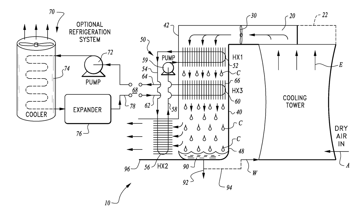
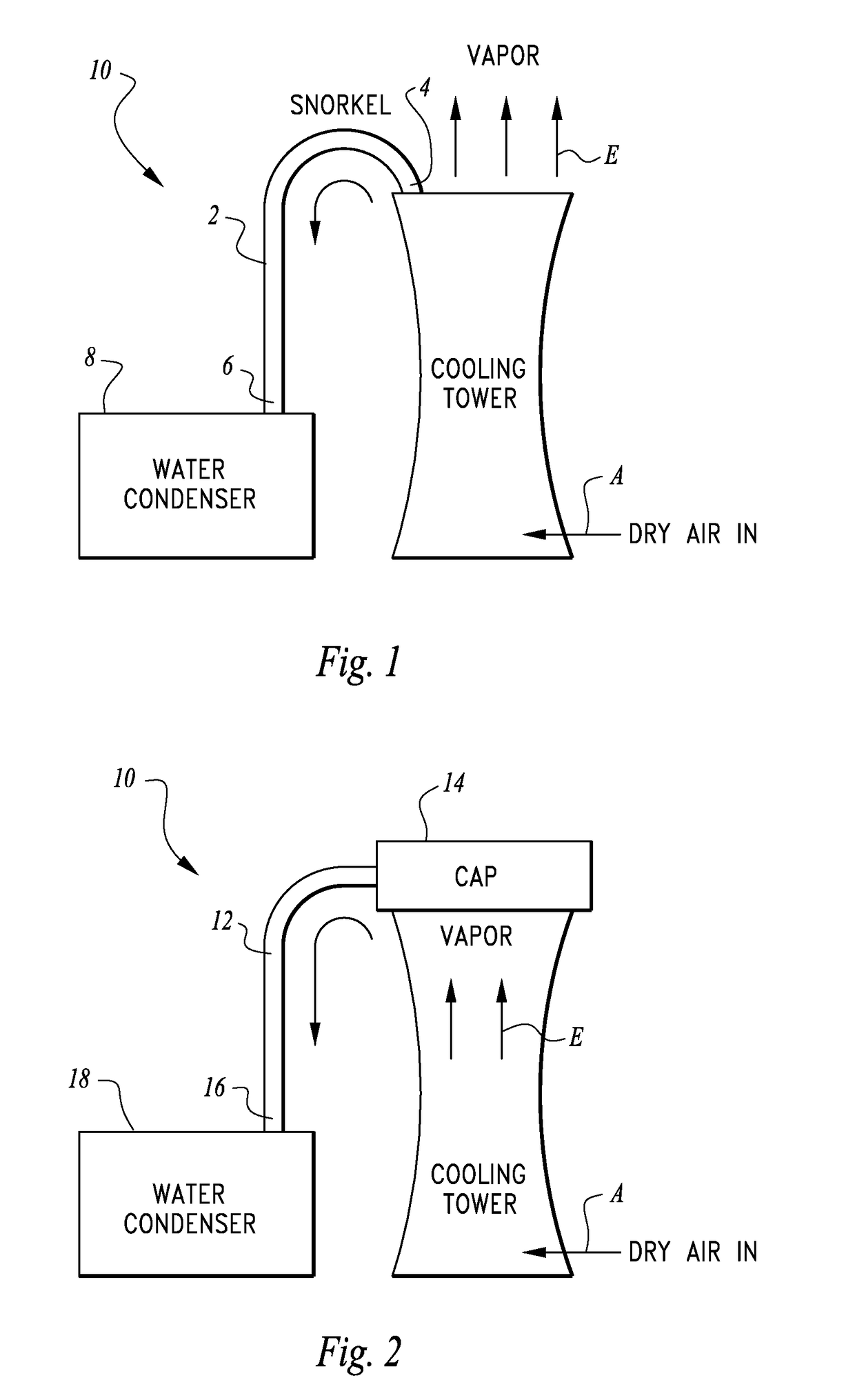
[0024]Referring to the drawings, wherein like reference numerals represent like parts throughout the various drawing figures, reference numeral 10 is directed to a water recovery system for collecting at least a portion of substantially saturated humid air from an exhaust of an evaporative cooling tower and then condensing water out of that substantially saturated humid air stream to recover water therefrom. The recovered water can be discharged from the system 10 or can be at least partially routed back to a water input W of the evaporative cooling tower to decrease water supply demands of the evaporative cooling tower.

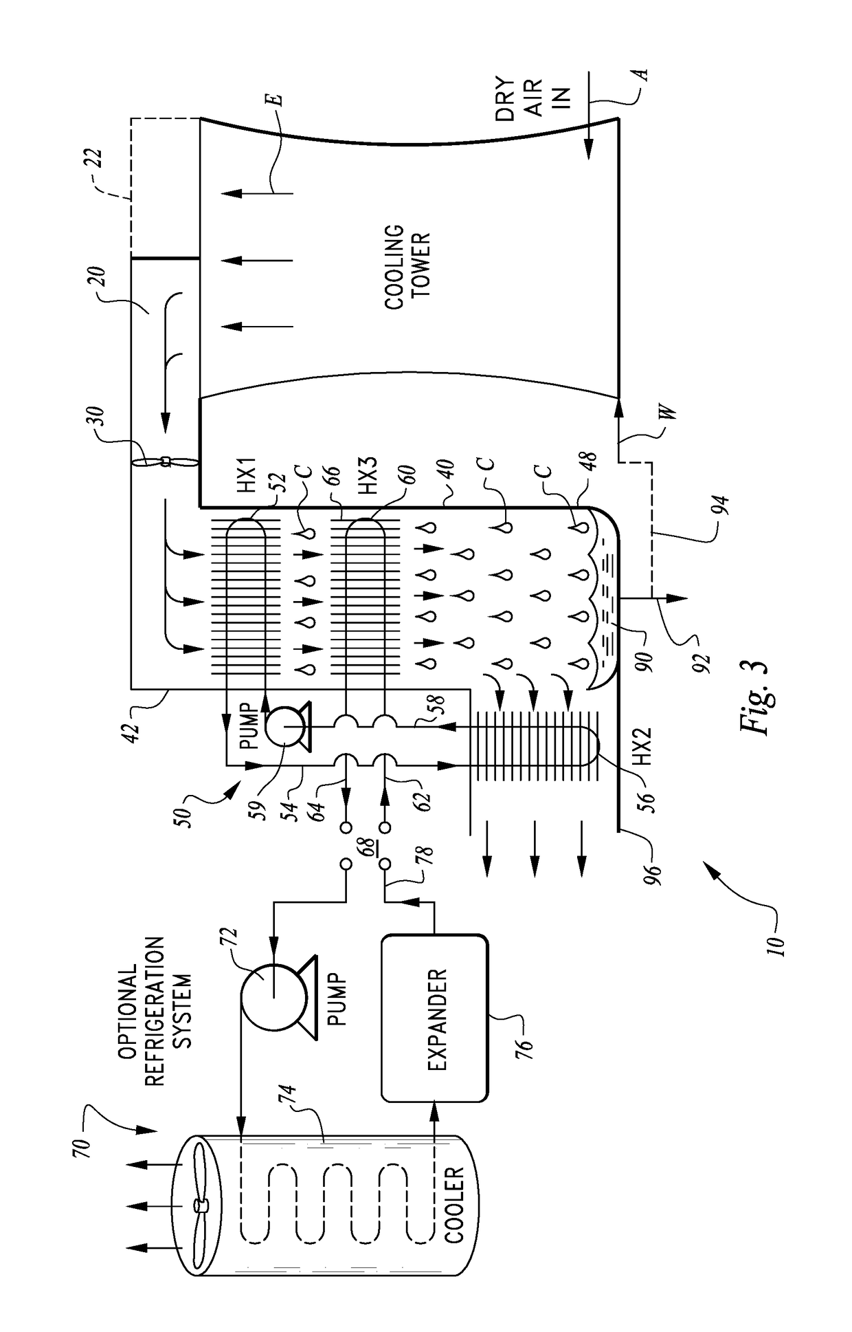
[0025]In essence, and with particular reference to FIG. 3, basic details of the system 10 are described, according to one exemplary embodiment. The water recovery system 10 is located adjacent to a cooling tower so that an entry hood 20 can capture at least a portion of the wet air exhaust E from the evaporative cooling tower. A fan 30 or other air mover is located d...


PUM


Abstract

To recover water from a cooling tower exhaust an air entry is provided adjacent thereto which feeds into a cooling heat exchanger. The cooling heat exchanger reduces a temperature of the wet air entering the air entry, causing condensation of water. This condensed water is captured and discharged from the system separate from dry air. A pre-cooler loop can be provided with a pre-cooler heat exchanger upstream of the cooling heat exchanger and fed by a cool line with a cold working fluid drawing heat out of the wet air. The pre-cooler heat exchanger can have its working fluid re-cooled in a second heat exchanger which exchanges heat with the cooler dry air downstream of the cooling heat exchanger. The cooling heat exchanger has a cold fluid passing therethrough which is cooled by a refrigeration system or some other cold fluid source.

Description

CROSS-REFERENCE TO RELATED APPLICATIONS[0001]This application claims benefit under Title 35, United States Code §119(e) of U.S. Provisional Application No. 62 / 235,668 filed on Oct. 1, 2015.FIELD OF THE INVENTION[0002]The following invention relates to water recovery systems for use with the substantially saturated humid air exiting an exhaust of a cooling tower. More particularly, this invention relates to water recovery systems which are fed with the substantially saturated humid air from an evaporative cooling tower, from small rooftop type units to large free standing units, and then dehumidify that air to produce a source of liquid water.BACKGROUND OF THE INVENTION[0003]Water is a precious commodity, especially water that is sufficiently pure to be utilized for landscaping, agriculture or as potable water. As water becomes more scarce and water demand increases, potential sources for reclaiming of usable water warrant investigation. Large volumes of water are involved in evapora...

Claims


Application Information

Patent Timeline
IPC IPC(8): F28F25/04F28C1/14F25B1/00F28C1/00
CPCF28F25/04F28C1/003F28F2025/005F25B1/00F28C2001/006F28C1/14F01K9/003F25B11/02F28B9/06F28F17/005Y02B30/70
Inventor LAMBERSON, JEFFERY M.
Owner PACIFIC AIRWELL CORP
Why Eureka
Try Eureka