Automatically heated catalytic converter

a catalytic converter and automatic technology, applied in the field of automatic heating catalytic converters, can solve the problems of global warming and become useless, and achieve the effect of reducing vehicle gas emission pollution and shortening the tim

Inactive Publication Date: 2017-04-13
INST TECHCO DE SANTO DOMINGO INTEC
View PDF3 Cites 0 Cited by
  • Summary
  • Abstract
  • Description
  • Claims
  • Application Information

AI Technical Summary

Benefits of technology

[0015]The object of the present invention is to provide a catalytic converter that reduces...

Problems solved by technology

This metal is a catalyzing oxidant, which acts upon CO (carbon monoxide) particles breaking their saturated bond due to high temperature in CO2 (carbon dioxide), harmless particles to the general public, ...

Method used


Image

  • Automatically heated catalytic converter
  • Automatically heated catalytic converter
  • Automatically heated catalytic converter

Examples


Embodiment Construction

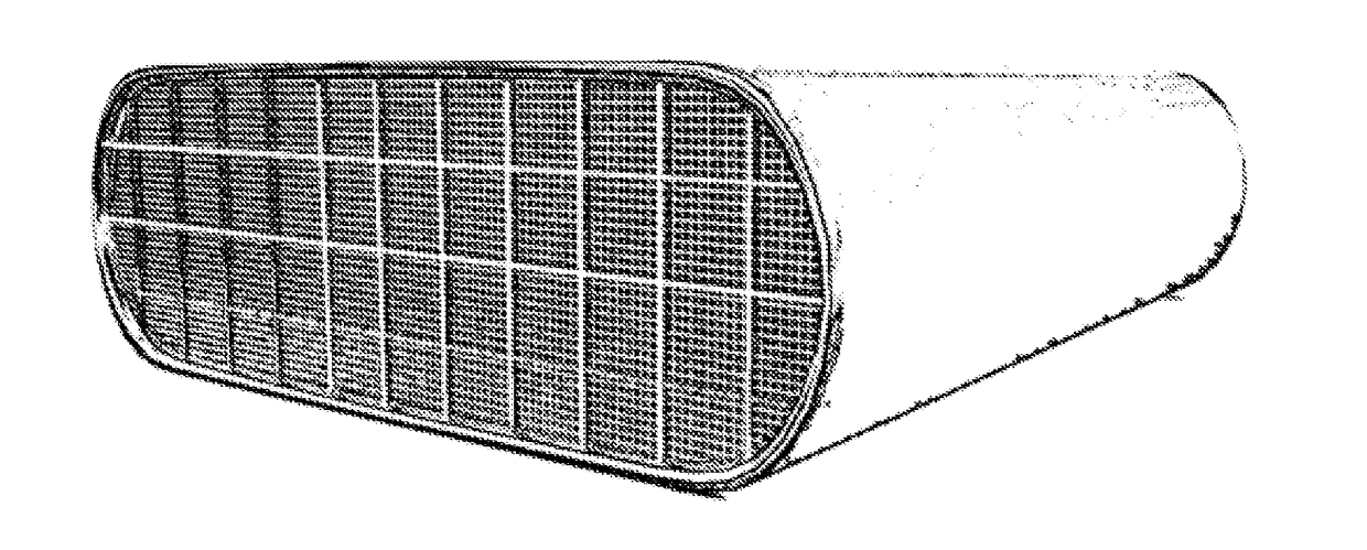
[0026]Our new catalytic converter, the automatic heating catalyzer (2) immediately the vehicle starts will commence to go into operation, reducing the direct pollution time up to a 90%. The essential is that the catalysts reach the working temperature regularly. Our device integrates heating resistors within the catalytic converter's monoliths in the shape of transversal lines along and across the monolith as it is illustrated by FIGS. 3 and 4. These lines, given their transversal nature among them, tend to form 100 mm2 squares each with a 0.05 mm line thickness with a 10 mm between margins for tolerance. The way to implement the internal heat resistors in that way, is because it is sought to increase the temperature gradient by reducing the time it takes for the resistors to heat their corresponding square. In other words, this way the heating area by square section is reduced thus increasing the heating efficiency and therefore the temperature gradient.

[0027]The resistors external...


PUM

PropertyMeasurementUnit
Electric potential / voltageaaaaaaaaaa
Areaaaaaaaaaaa
Lengthaaaaaaaaaa

Abstract

The present invention is based on the application of heating resistors by a temperature regulation circuit in certain points of the catalyzer so that this comes into operation in the least time possible, reducing most of the amount of low molecular stability or environmentally harmful substances. Likewise, little tumult are added to each monolith duct to raise exhaust gas turbulence and increase the contact between the reduction and oxidation agent, whether it be platinum, palladium and rhodium.

Description

CROSS REFERENCE TO RELATED APPLICATION[0001]This application is a national stage entry of PCT / D02015 / 000003 filed Aug. 17, 2015, under the International Convention claiming priority over Dominican Republic Patent Application No. U2014-0190 filed Aug. 18, 2014.FIELD OF THE INVENTION[0002]The present invention relates to the catalytic converters implemented in vehicles with internal combustion engines (7) that make low molecular stability particles and polluters such as carbon monoxide, unburnt hydrocarbons, sulfur and nitrogen oxide react in order to recombine them in harmless particles to the environment. The utility model entirely relates to the device or catalytic converter implementing onto it an automatic temperature control circuit (1) and heat resistance to accelerate the speed of the reactions.BACKGROUND OF THE INVENTION[0003]Catalysts are substances that vary the speed of a chemical reaction without being consumed therein. Once a chemical reaction has been produced the catal...

Claims


Application Information

Patent Timeline
IPC IPC(8): F01N3/20B01D53/94B01J35/04
CPCF01N3/2026B01J35/04B01D2255/1023B01D2255/1021B01D2255/1025B01D53/94B01D53/9454B01D2257/404B01D2257/502B01D2257/702B01D2258/01F01N3/10F01N3/101F01N3/103F01N3/106F01N3/2013F01N3/28F01N3/2892F01N9/00F01N2240/16F01N2240/20F01N2570/10F01N2570/12F01N2570/14F01N13/0097Y02A50/20Y02T10/12Y02T10/40
Inventor BENCOSME FERRERAS, FRANCARLOSFIGUEROA GUICHARDO, KEYRON
Owner INST TECHCO DE SANTO DOMINGO INTEC
Why Eureka
Try Eureka