
Modular bone screw for surgical fixation to bone

a bone screw and module technology, applied in the field of surgical bone screws, can solve the problems of difficult to create a stable and secure attachment point, difficult task, and interfere with the proper placement of the screw into the bone, and achieve the effects of tissue fixation, enhanced anchoring stability, and compatibility with a driver

Active Publication Date: 2017-04-27
REGENIMMUNE INC
View PDF21 Cites 9 Cited by
  • Summary
  • Abstract
  • Description
  • Claims
  • Application Information

AI Technical Summary

Benefits of technology

The patent text describes a new design for a screw used in orthopedic surgery. This new design is a single piece that combines the functions of two separate screws, making it stronger and easier to fix to tissue. It is also compatible with a driver, a special tool used in surgery. This new design allows for better stability and tissue fixation in a single unit.

Problems solved by technology

Creating a stable and secure attachment point is difficult because the bone tissue must support large mechanical forces and the attachment of synthetic or graft structures to bone places enormous stress on both the bone and the attachment device at the point of attachment or fixation.
The problem with current surgical screws is that the graphs or devices, which are typically being anchored to bone at the target site, interfere with visualization of underlying bone at the target site and can interfere with the proper placement of the screw into bone.
Also, many surgical procedures, and particularly dental procedures, require precise placement of bone in confined spaces with delicate bone and tissue structures and difficult geometrics.
The task is particularly challenging with the limited fields of view inherent in dental applications, such as when placing an anchor, where visualization of the attachment of the fixture takes place between teeth and requires careful and stable securing of the structure to the jaw bone.
Thus, the existing surgical practices and apparatus have at least the following drawbacks: 1) the attachment structure must be held in place while the threaded portion of the screw is drilled into the bone under limited visibility; 2) the placement can be inaccurate and often damage the bone when the underlying bone is visually blocked by the screw, the attachment structure, or both; 3) driving a screw through surrounding membranes can cause the membrane to rotate and the attachment between the driver and the screw is generally unstable.

Method used


Image

  • Modular bone screw for surgical fixation to bone
  • Modular bone screw for surgical fixation to bone
  • Modular bone screw for surgical fixation to bone

Examples


Embodiment Construction

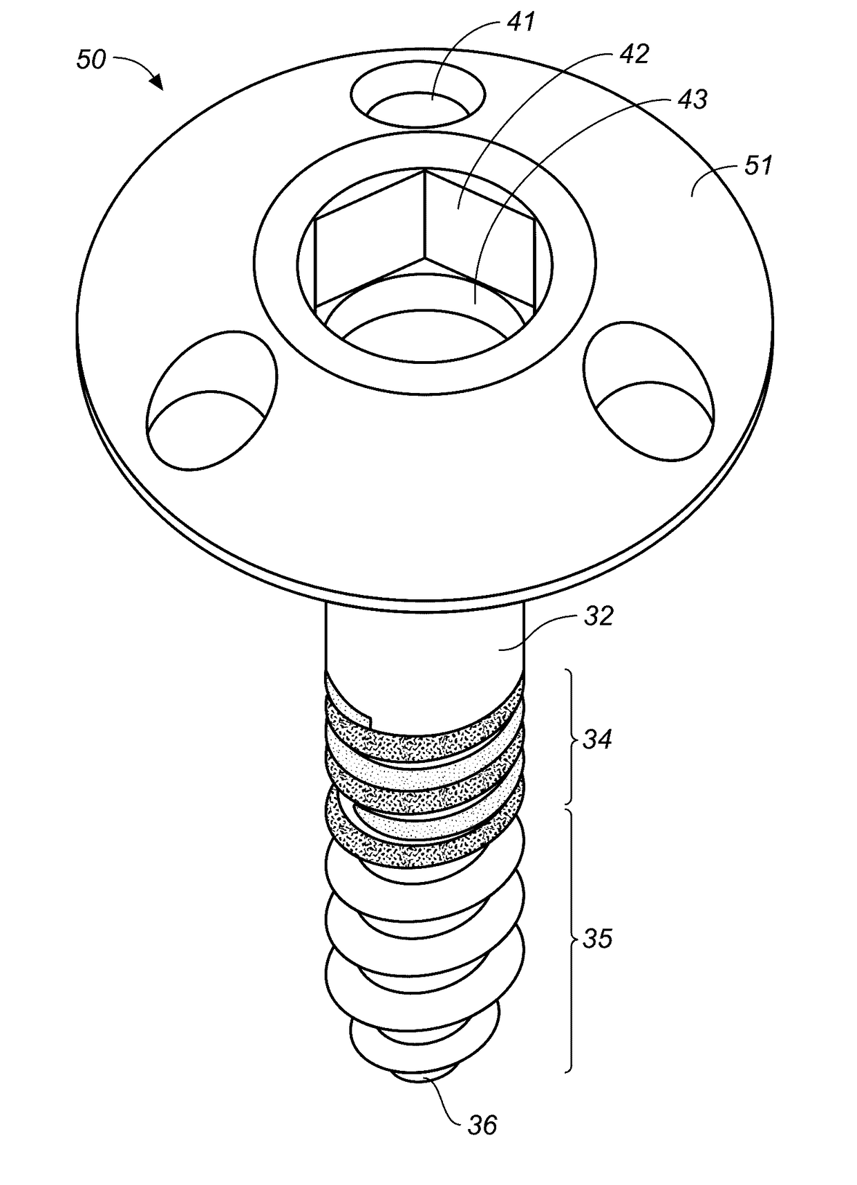
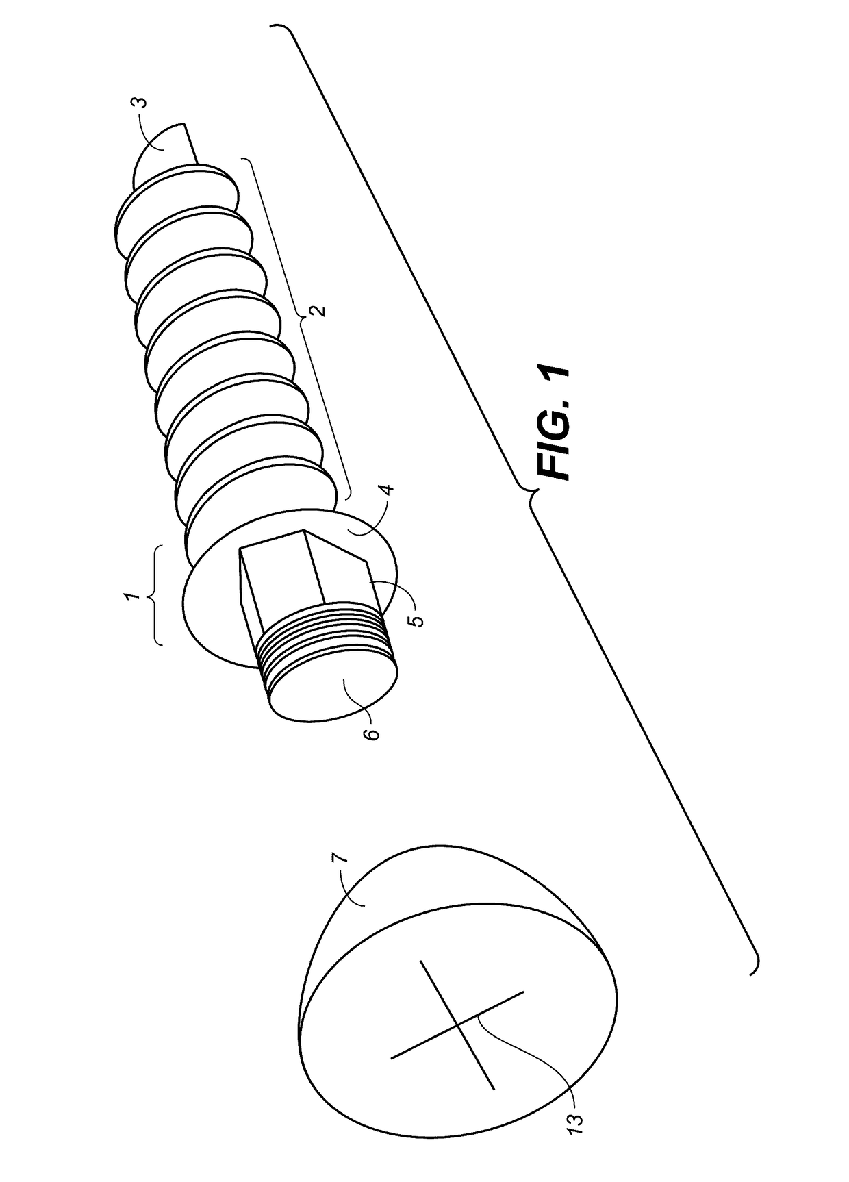
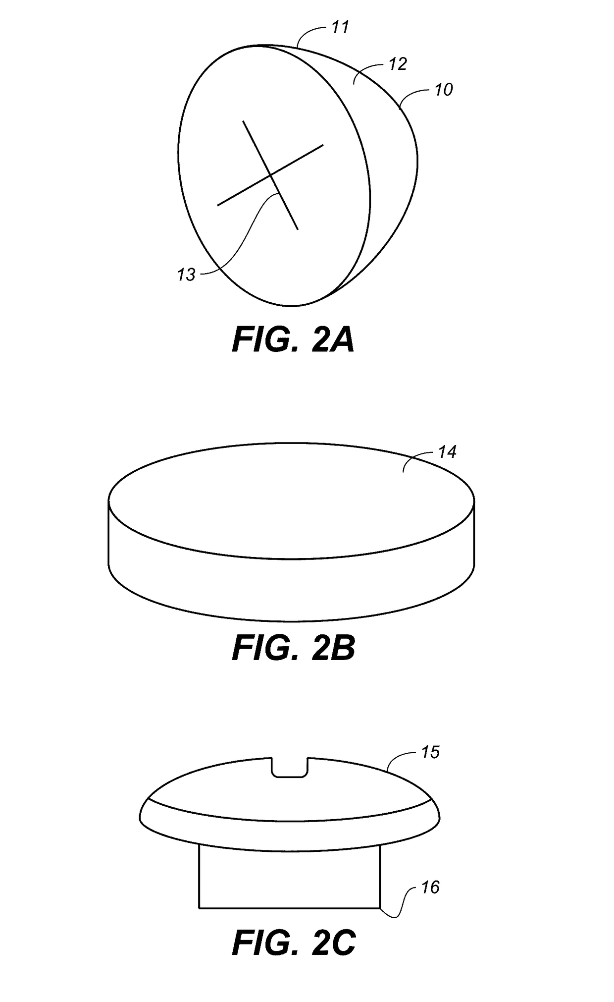
[0017]The screw assembly for bone surgery according to the present invention provides a modular assembly comprised of a threaded screw base piece having a distal threaded portion terminating in a tip and a proximal portion for affixation to a screw head. The screw also be comprised of a non-threaded portion along an axial length thereof. The most proximal portion of the screw may also have means for attachment of a cap, engaging a driver, or in engaging means is preferably recessed into the headpiece. In the alternative embodiment, the means for engaging the driver is disposed in the upper surface of the. In the multi-piece assembly embodiments, the cap is designed to engage both the driver at the upper portion, typically through a hex fixture, while the bottom portion has an internal thread to engage the proximal portion of the screw or screw base. Depending on the purpose of the cap, various configurations for the cap of the screw assembly can be attached or mounted to a correspon...


PUM


Abstract

The invention discloses a modular surgical bone screw assembly having a threaded base portion and a screw head adapted to attach a variety of structures to bone. The features of the screw include a modular design for the assembly that separates the function of anchorage to the recipient bone to one of the modules of the device (threaded portion) from the other function of attaching another element (such as bone block, membrane, orthodontic wires, elastics etc) to a second module (the screw head). The design also allows the head to be exchanged after the implant has been placed.

Description

PRIORITY[0001]This application claims priority to U.S. Provisional application Ser. No. 62 / 234,008, which is specifically incorporated herein by reference.FIELD OF THE ART[0002]The present invention is in the field of surgical bone screws used for attachment of structure or fixation of bone during surgery.BACKGROUND[0003]A wide variety of surgical applications require the placement of surgical screws in bone tissue. Some procedures use bone tissue as an attachment point for other devices such as titanium mesh, orthodontic anchors, resorbable or nonresorbable membranes. Other procedures require attachment of bone graft to host bone, such as the fixation of a bone block or graft or stabilization of a fracture. It is often necessary to stabilize soft tissues such as mucosa, skin, muscle or tendon, in which case bone provides a stable anchorage onto which soft tissues can be attached. Creating a stable and secure attachment point is difficult because the bone tissue must support large m...

Claims


Application Information

Patent Timeline
IPC IPC(8): A61B17/86A61F2/08A61B17/04
CPCA61B17/8605A61B17/8685A61B17/863A61B17/0401A61F2002/0852A61B2017/0464A61B2017/044A61B2017/0414A61F2002/0829A61F2/0811A61F2002/0888A61C8/0025A61C8/008A61C8/0096A61C8/0022
Inventor ZADEH, HOMAYOUN H.
Owner REGENIMMUNE INC
Learn More