
Power amplification system for radiofrequency communications

Active Publication Date: 2017-04-27
TEKO TELECOM
View PDF4 Cites 0 Cited by
  • Summary
  • Abstract
  • Description
  • Claims
  • Application Information

AI Technical Summary

Benefits of technology

The present invention aims to provide a power amplification system for radiofrequency communications that can improve RF signal amplification. Additionally, the invention seeks to overcome the shortcomings of the prior art while maintaining a simple, easy-to-use and affordable solution.

Problems solved by technology

In particular, one of the biggest challenges in designing modem wireless transceivers consists in the trade-off between linearity and efficiency of RF amplifiers.
On the one hand, in fact, spectrally efficient modulated signals, such as W-CDMA (Wideband Code Division Multiple Access) and OFDM (Orthogonal Frequency-Division Multiplexing) signals, affect the non-linearity of the amplifier, with consequent undesired in-band distortions and out-of-band spectral re-growth.
Such distortions therefore involve the violation of the narrow requirements defined by communication standards.
To this must be added the fact that the use of a simple direct-conversion transmitter is not practical for three main reasons.
Furthermore, a direct-conversion system is very sensitive to gain imbalance and to phase and DC voltage offset errors of the modulator in quadrature.
Such technique is not without its drawbacks however inasmuch as it calls for identical paths for the way I and the way Q which cannot be achieved in analog ambit.
The gain imbalance and the phase difference between the I and Q paths involve spurious signals that again fall within the transmission band and which cannot be filtered by means of RF or digital filters.
Neither of the spurious components are negligible and both considerably affect the correct operation of the amplifier.
Nevertheless, the errors relating to the continuous component, to the offset and to the phase can increase according to the temperature and time.

Method used


Image

  • Power amplification system for radiofrequency communications
  • Power amplification system for radiofrequency communications
  • Power amplification system for radiofrequency communications

Examples


Embodiment Construction

[0028]The main aim of the present invention is to provide a power amplification system for radiofrequency communications which allows better performance in the RF signal amplification.

[0029]Another object of the present invention is to provide a power amplification system for radiofrequency communications that allows to overcome the mentioned drawbacks of the prior art within the ambit of a simple, rational, easy and effective to use as well as affordable solution.

[0030]The above mentioned objects are achieved by the present power amplification system for radiofrequency communications according to the characteristics described in claim 1.

BRIEF DESCRIPTION OF THE DRAWINGS

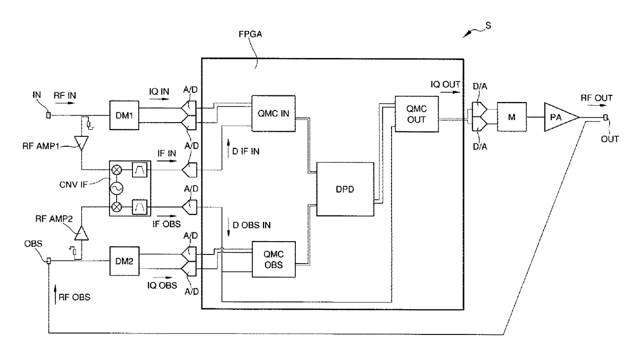
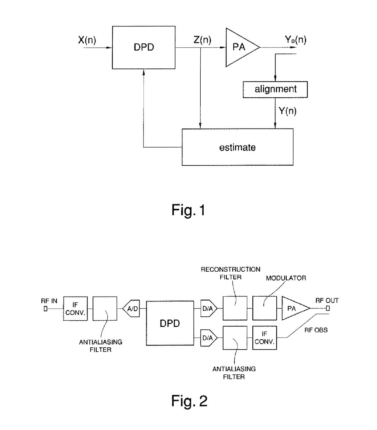
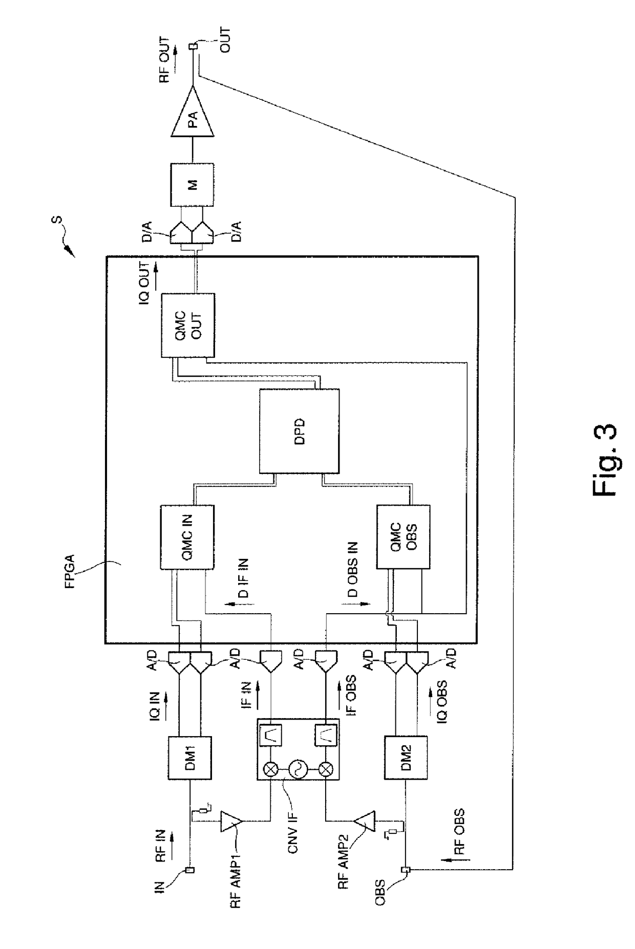
[0031]Other characteristics and advantages of the present invention will become better evident from the description of a preferred, but not exclusive embodiment of a power amplification system for radiofrequency communications, illustrated by way of an indicative, but non-limiting example in the accompanying drawings...


PUM


Abstract

Power amplification system for radio frequency communications, comprising a input port of an input radio frequency signal, an output port of an output radio frequency signal; a digital predistortion unit operatively interposed between the input port and the output port and quadrature modulation correction means operatively interposed between the digital predistortion unit and between at least one of the input port and the output port.

Description

TECHNICAL FIELD[0001]The present invention relates to a power amplification system for radiofrequency communications.BACKGROUND ART[0002]Within the scope of mobile communications, considerable efforts have been made in order to use linear modulation techniques to improve spectral and power efficiency.[0003]In particular, one of the biggest challenges in designing modem wireless transceivers consists in the trade-off between linearity and efficiency of RF amplifiers.[0004]On the one hand, in fact, spectrally efficient modulated signals, such as W-CDMA (Wideband Code Division Multiple Access) and OFDM (Orthogonal Frequency-Division Multiplexing) signals, affect the non-linearity of the amplifier, with consequent undesired in-band distortions and out-of-band spectral re-growth. Such distortions therefore involve the violation of the narrow requirements defined by communication standards.[0005]On the other hand, the improvement of the efficiency of the amplifiers results in a significan...

Claims


Application Information

Patent Timeline
IPC IPC(8): H03F1/32H04B1/04H04B1/00H03F3/189H03F3/24
CPCH03F1/3247H03F3/189H03F3/24H04B2001/0408H04B1/0475H03F2200/336H03F2200/451H04B1/0014H03F2200/132H03F2200/204H03F2200/207H04L27/368
Inventor DURANTE, DAVIDENOTARGIACOMO, MASSIMOCHIURCO, GIOVANNIMARTELLI, FLAVIA
Owner TEKO TELECOM
Learn More