Supercharge Your Innovation With Domain-Expert AI Agents!

Baw sensor with enhanced surface area active region

a surface area active region and sensor technology, applied in the direction of instruments, analysing fluids using sonic/ultrasonic/infrasonic waves, laboratory glassware, etc., can solve the problem that analyte present in fluid layers other than the lowermost fluid layer may not be available for binding with the functionalization material along the bottom surface of the microfluidic channel, and the diffusion process is typically slow. problem, to achieve the effect of reducing the diffusion distance, increasing the non-

Active Publication Date: 2017-05-11
QORVO US INC
View PDF3 Cites 7 Cited by
  • Summary
  • Abstract
  • Description
  • Claims
  • Application Information

AI Technical Summary

Benefits of technology

The present patent provides a MEMS resonator device that includes a piezoelectric material arranged between a top side electrode and a bottom side electrode, and a patterned enhanced surface area element arranged between the top side electrode and a functionalization material. The patterned enhanced surface area element increases non-planarity of the functionalization material, providing a three-dimensional structure that increases sensor surface area and reduces analyte diffusion distance to improve sensor performance. The device also includes a hermeticity layer, an interface layer, a self-assembled monolayer, or a support layer. The device can be used in fluidic devices for biological or chemical sensing.

Problems solved by technology

Multiple fluids introduced in a standard microfluidic channel generally will not mix with each other, except at a common interface between the fluids via diffusion, and the diffusion process is typically slow compared with the flow of fluid along a principal axis of a microfluidic channel.
But since diffusion is slow in a direction perpendicular to the direction of fluid flow through the microfluidic channel, and analyte needs to diffuse to a surface bearing functionalization material to bind, analyte present in fluid layers other than the lowermost fluid layer may not be available for binding with the functionalization material along the bottom surface of the microfluidic channel within a reasonable period of time.

Method used


Image

  • Baw sensor with enhanced surface area active region
  • Baw sensor with enhanced surface area active region
  • Baw sensor with enhanced surface area active region

Examples


Embodiment Construction

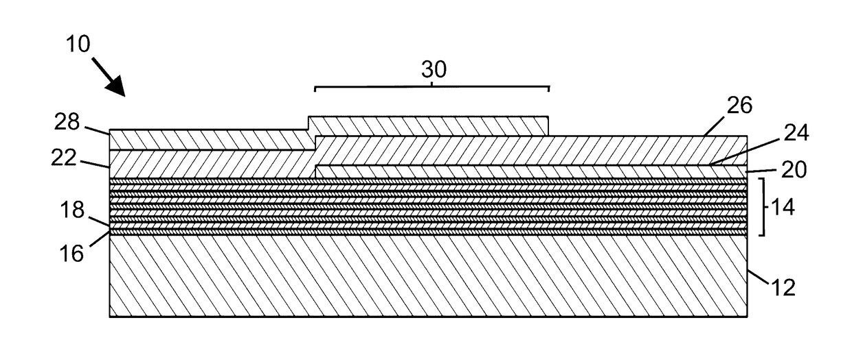
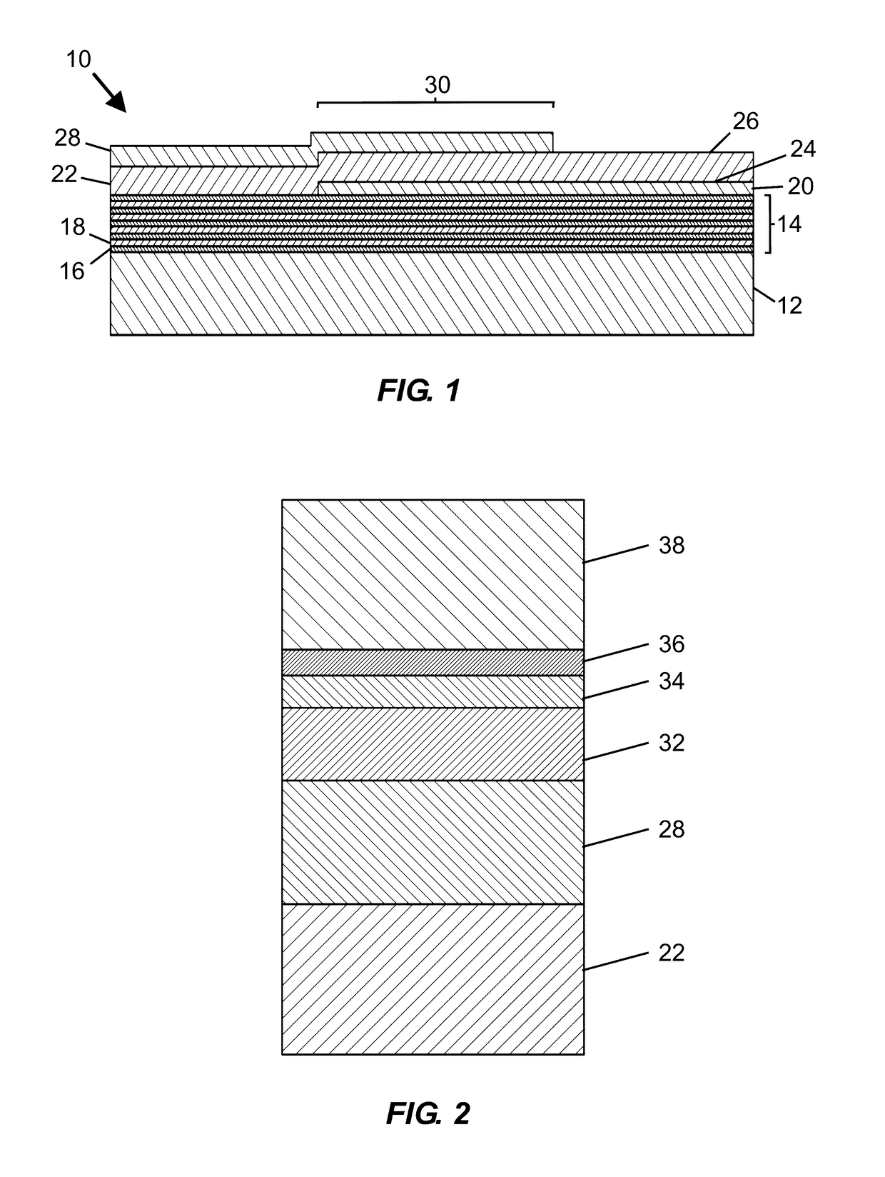
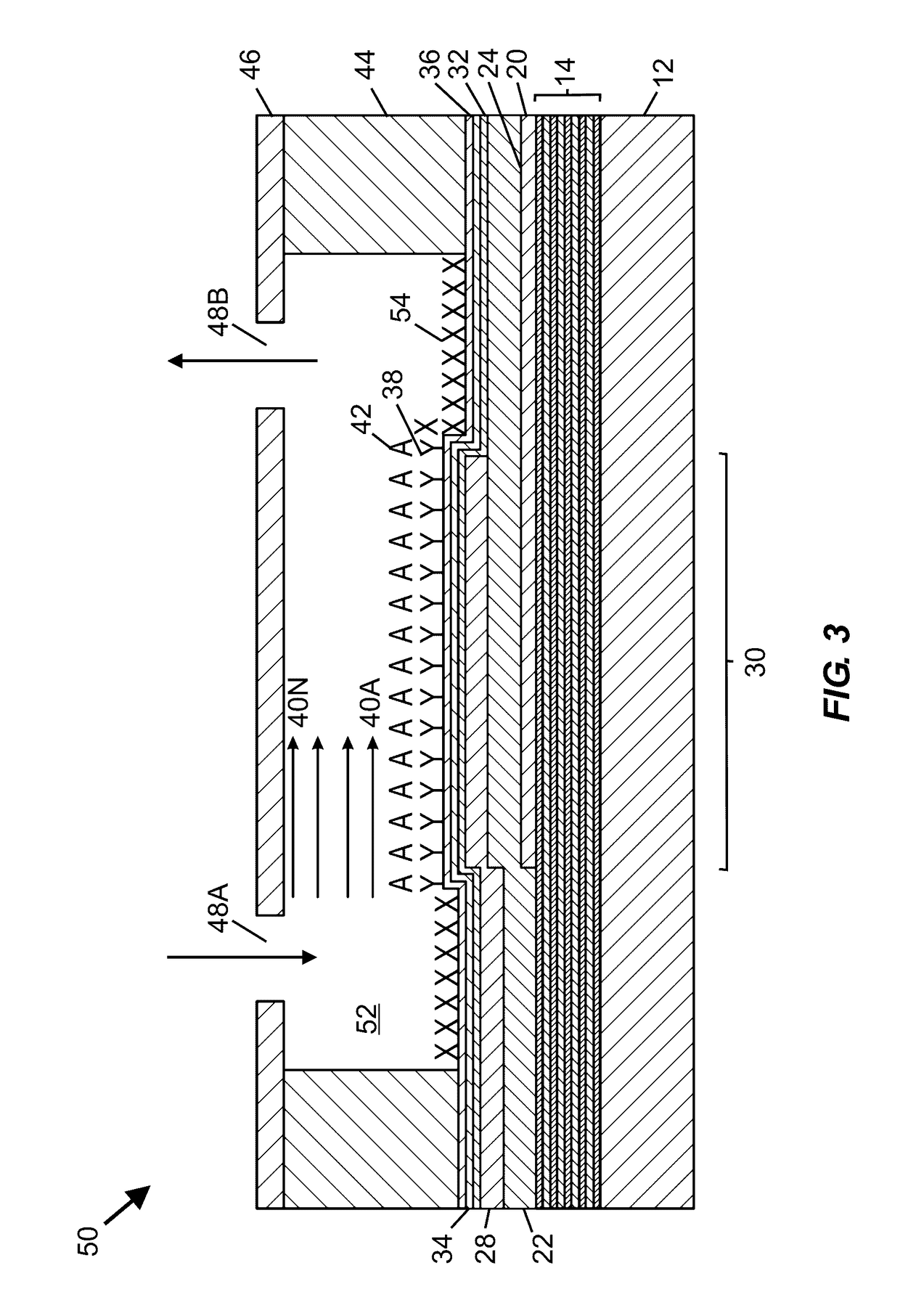
[0051]The embodiments set forth below represent the necessary information to enable those skilled in the art to practice the embodiments and illustrate the best mode of practicing the embodiments. Upon reading the following description in light of the accompanying drawing figures, those skilled in the art will understand the concepts of the disclosure and will recognize applications of these concepts not particularly addressed herein. It should be understood that these concepts and applications fall within the scope of the disclosure and the accompanying claims.

[0052]It should be understood that, although the terms first, second, etc. may be used herein to describe various elements, these elements should not be limited by these terms. These terms are only used to distinguish one element from another. For example, a first element could be termed a second element, and, similarly, a second element could be termed a first element, without departing from the scope of the present disclosu...


PUM


Abstract

A bulk acoustic wave MEMS resonator device includes at least one functionalization (e.g., specific binding or non-specific binding) material arranged over a top side electrode, with at least one patterned enhanced surface area element arranged between a lower surface of the top side electrode and the functionalization material. The at least one patterned enhanced surface area element increases non-planarity of the at least one functionalization material, thereby providing a three-dimensional structure configured to increase sensor surface area and reduce analyte diffusion distance, and may also promote fluid mixing. Methods for biological and chemical sensing, and methods for forming MEMS resonator devices and fluidic devices are further disclosed.

Description

STATEMENT OF RELATED APPLICATIONS[0001]This application is a non-provisional of provisional patent application Ser. No. 62 / 252,688, filed Nov. 9, 2015, the disclosure of which is hereby incorporated herein by reference in its entirety. Subject matter disclosed herein also relates to U.S. patent application Ser. No. ______ entitled “Multi-Frequency BAW Mixing and Sensing System and Method” filed or to be filed on Oct. 31, 2016, the contents of which are hereby incorporated by reference as if set forth fully herein.TECHNICAL FIELD[0002]The present disclosure relates to fluidic devices incorporating acoustic resonators, including fluidic devices and related systems suitable for biosensing or biochemical sensing applications.BACKGROUND[0003]A biosensor (or biological sensor) is an analytical device including a biological element and a transducer that converts a biological response into an electrical signal. Certain biosensors involve a selective biochemical reaction between a specific b...

Claims


Application Information

Patent Timeline
IPC IPC(8): H03H9/17G01N29/22G01N33/543G01N29/02H03H3/02B01L3/00
CPCH03H9/17H03H3/02B01L3/502715B01L3/502761B01L3/502707B01L2300/0887G01N29/022G01N29/222H03H2003/027B01L2200/12B01L2300/0645G01N33/5438G01N29/2437G01N2291/0255G01N2291/0256G01N2291/0426G01N2291/012G01N2291/014H03H9/175G01N2291/015
Inventor RIVAS, RIOANDRUS, CRAIG
Owner QORVO US INC
Features
  • R&D
  • Intellectual Property
  • Life Sciences
  • Materials
  • Tech Scout
  • Unparalleled Data Quality
  • Higher Quality Content
  • 60% Fewer Hallucinations
Learn More