
Frequency doubler having optimized harmonic suppression characteristics

a frequency doubler and harmonic suppression technology, applied in the field of frequency doublers, can solve the problems of difficult implementation of frequency doublers, bad harmonic suppression characteristics, and difficult to achieve, and achieve the effect of minimizing undesired harmonic characteristics

Inactive Publication Date: 2017-05-18
ELECTRONICS & TELECOMM RES INST
View PDF3 Cites 4 Cited by
  • Summary
  • Abstract
  • Description
  • Claims
  • Application Information

AI Technical Summary

Benefits of technology

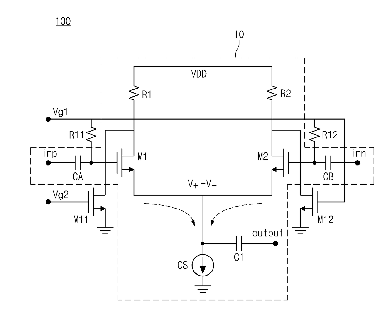
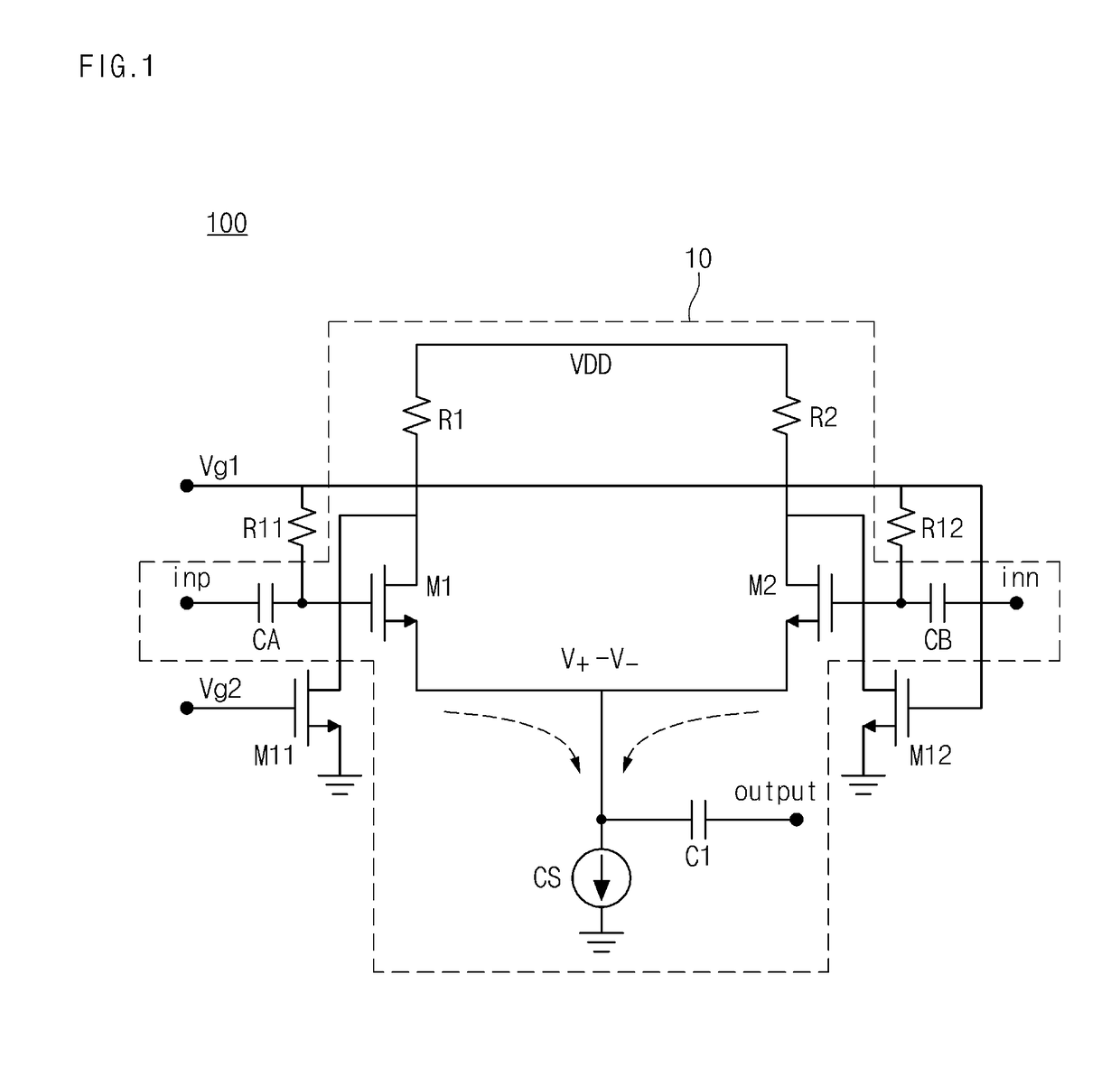
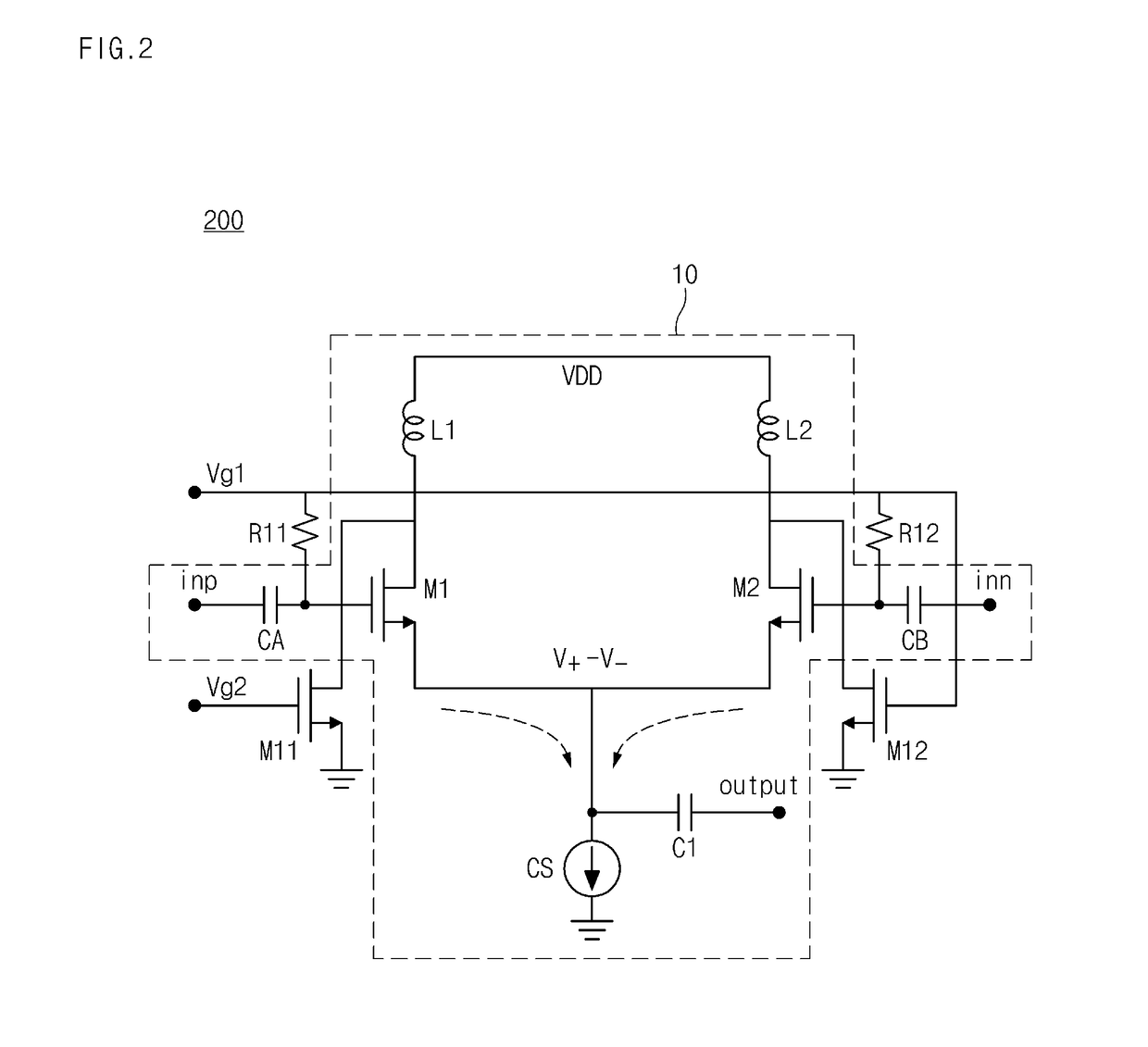
The present invention provides a frequency douler that controls the signal to a virtual ground by adjusting the gain of one-side transistor among transistors receiving differential input signals. This helps to minimize undesired harmonics characteristics in a frequency doubled signal output. The frequency douler uses a differential circuit structure and optimizes harmonics suppression characteristics by adjusting the bias of an auxiliary transistor or one-side transistor of a differential amplifier. This results in a more efficient and accurate frequency doubling process.

Problems solved by technology

A frequency doubler is one of the core components for generating an LO signal in a high frequency band, but is not easily implemented due to various causes including a limit in process, and the like.
A CMOS based frequency doubler reported in the related art may be implemented by not a differential scheme but a single scheme, but generally has a disadvantage in that harmonic suppression characteristics are bad.
Further, it is reported that a differential scheme structure through an inverter type amplifier is used, but this also has a disadvantage in that the harmonic suppression characteristics become degraded due to an element layout and a parasitic error.
However, in the frequency multiplication using the CMOS based differential circuit structure in the related art, an undesired odd mode harmonics signal is generated on the virtual ground due to amplitude mismatch of the differential input signal, and as a result, an undesired harmonics signal is included in the frequency multiplied signal.

Method used


Image

  • Frequency doubler having optimized harmonic suppression characteristics
  • Frequency doubler having optimized harmonic suppression characteristics
  • Frequency doubler having optimized harmonic suppression characteristics

Examples


Embodiment Construction

[0030]Hereinafter, some exemplary embodiments of the present invention will be described in detail with reference to the exemplary drawings. When reference numerals refer to components of each drawing, it is noted that although the same components are illustrated in different drawings, the same components are designated by the same reference numerals as possible. In describing the exemplary embodiments of the present invention, when it is determined that the detailed description of the known components and functions related to the present invention may obscure understanding of the exemplary embodiments of the present invention, the detailed description thereof will be omitted.

[0031]Terms such as first, second, A, B, (a), (b), and the like may be used in describing the components of the exemplary embodiments of the present invention. The terms are only used to distinguish a component from another component, but nature or an order of the component is not limited by the terms. Further,...


PUM


Abstract

Disclosed is a frequency doubler which controls a magnitude of a signal supplied to a virtual ground by adjusting a gain of one-side transistor among transistors receiving differential input signals when outputting a frequency multiplied LO signal through the virtual ground by amplifying the input differential signals by using a differential circuit structure to minimize undesired harmonics characteristics in a frequency doubled signal output by making the magnitudes of two differential signals be the same as each other.

Description

CROSS-REFERENCE TO RELATED APPLICATIONS[0001]This application claims priority to and the benefit of Korean Patent Application No. 10-2015-0161911 filed in the Korean Intellectual Property Office on Nov. 18, 2015, the entire contents of which are incorporated herein by reference.TECHNICAL FIELD[0002]The present invention relates to a frequency doubler, and particularly, to a frequency doubler which integrates a module that can generate a local oscillator (LO) signal which is frequency multiplied in a high frequency band by overcoming a frequency limit in a CMOS process and optimizing harmonic suppression characteristics by the CMOS process to be implemented on a chip.BACKGROUND ART[0003]A frequency doubler is one of the core components for generating an LO signal in a high frequency band, but is not easily implemented due to various causes including a limit in process, and the like. A CMOS based frequency doubler reported in the related art may be implemented by not a differential sc...

Claims


Application Information

Patent Timeline
IPC IPC(8): H03K3/013H03G1/00H03K5/00
CPCH03K3/013H03G1/0029H03K5/00006H03G3/3052
Inventor MOON, SEONG MOYOM, IN BOK
Owner ELECTRONICS & TELECOMM RES INST
Learn More