Wear-resistant roller

a technology of wear-resistant rollers and rollers, which is applied in the direction of plasma welding apparatus, welding/soldering/cutting articles, manufacturing tools, etc., can solve the problems of high installation or maintenance cost of studded technology, high cost of studs, so as to reduce the welding speed of the second welding, increase the dwell time of welding, and slow down the effect of welding speed

Active Publication Date: 2017-05-25
F L SMIDTH & CO AS
View PDF3 Cites 1 Cited by
  • Summary
  • Abstract
  • Description
  • Claims
  • Application Information

AI Technical Summary

Benefits of technology

[0041]Also, a speed of welding the second welding may be lowered during welding in the turn point region thereby increasing a welding dwell time in the turn point region.
[0042]Slowing down the welding speed in the turning point regions increases the dwell time allowing improved up-concentration of carbide material in the overlapping region.
[0043]Further, a welding current during welding of the second welding is increased during welding in the turn point region thereby increasing an energy input to the overlapping region in the turn point region.
[0044]Increasing the welding current in the turning point regions increases the energy input thereby increasing temperature and mobility of carbide particles in the metal matrix allowing improved up-concentration of carbide material in the overlapping region.

Problems solved by technology

Using studded technologies is often too expensive either to install or maintain, and often also inadequate when working with very high pressures such as in roller mills or roller crushers due to failure of attachment to the roller body.
The wear-resistant material of which the studs are made is very expensive and since a part of each stud is embedded in the roller for fastening the stud, and only a smaller portion of the stud protrudes from the roller surface and is actually utilized as wear-resistant material, most of the expensive material is not subjected to wear, which is a poor utilization of the wear-resistant material.
However, a well-known disadvantage of hardfacing is the lack of gripping capability when a hard-faced surface is worn sometimes even only slightly worn.
Wear on hard-faced surfaces typically results in the wear surface very quickly becoming completely smooth drastically decreasing the crushing effectiveness of the roller.

Method used


Image

  • Wear-resistant roller
  • Wear-resistant roller
  • Wear-resistant roller

Examples


example 1

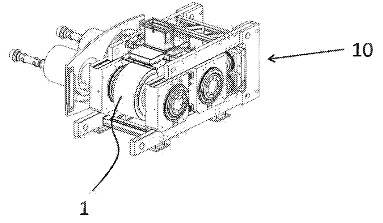
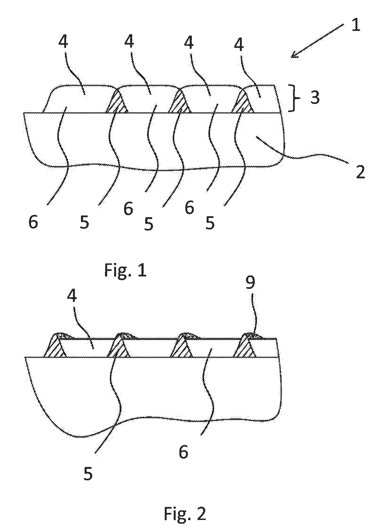
[0071]The described invention has been industrially proven by welding a wear surface onto a set of grinding rollers. The welding beads of the wear surfaces were welded in tangential direction next to each other across the roller width. Each welding bead had a height of approximately 3 mm and a width of approximately 16 mm width an overlap of approximately 2 mm in each side of the welding bead such that the non-overlapping volumes was approximately 12 mm wide and the overlapping volumes was approximately 2 mm. The material of the wear surface was a Nickel-Tungsten blend with fused Tungsten carbides having a corresponding weight percentage of 40 wt. % Nickel and 60 wt. % Tungsten. The material was welded to the roller body using a Plasma Transfer Arc welding process.

[0072]The wear surface comprised four layers of welding beads of 3 mm in height and thus constituted a total wear surface height of approximately 12 mm. The layers are positioned such that non-overlapping and overlapping v...

example 2

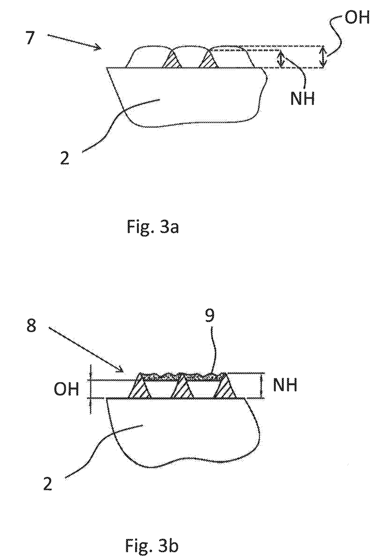
[0075]Occurrence of the micro-texture effect is not dependent on the characteristics of feed material, i.e. the type of mineral being grinded. Harder minerals than cement clinker like mineral ores also imply selective wear of the welding beads; the overlapping regions wears less than the non-overlapping of the beads leading to a surface texture having the feature of retaining fines thus create autogenous layers. The autogenous layers mean less overall wear and higher friction of the roller surface which is beneficial for the productivity of the grinding operation. Very hard and abrasive minerals ores like Co, Fe or diamond enriched ones tends to increase the difference of wear rate between the two regions implying that the protruding height of the overlapping sections even increase compared to grinding less hard and abrasive minerals as for example cement clinker. However in case of the more hard and abrasive ores, the protruding sections are smoothen out resulting in a wavy shape w...


PUM

PropertyMeasurementUnit
distanceaaaaaaaaaa
widthaaaaaaaaaa
widthaaaaaaaaaa

Abstract

The invention relates to a wear-resistant roller for crushing of particulate material, such as crude ore for use in the cement or minerals industry comprising a roller body, a wear surface on the roller body. The wear surface comprises welding beads comprising a primary fraction of carbide material and a secondary fraction of material selected from the group consisting of Nickel, Nickel alloys, mixtures of Nickel and Nickel alloys and mixtures of Nickel containing refractory hard materials, Cobalt, Cobalt alloys, mixtures of Cobalt and Cobalt alloys and mixtures of Cobalt containing refractory hard materials. Furthermore, the welding beads are welded to the roller body in an overlapping manner such that two neighbouring welding beads comprise an overlapping volume and a non-overlapping volume, the overlapping volume being an intersection volume between the two neighbouring overlapping welding beads, and the fraction of carbide material being higher in the overlapping volume than in the non-overlapping volume such that the overlapping volume has a higher wear resistance compared to the non-overlapping volume having a lower wear-resistance. Also the invention relates to a method of forming such a wear surface on a roller body.

Description

FIELD OF THE INVENTION[0001]The present invention relates to a wear-resistant roller for crushing of particulate material, such as crude ore for use in the cement or minerals industry comprising a roller body, a wear surface on the roller body. The wear surface comprises welding beads comprising a primary fraction of carbide material and a secondary fraction of material selected from the group consisting of Nickel, Nickel alloys, mixtures of Nickel and Nickel alloys and mixtures of Nickel containing refractory hard materials, Cobalt, Cobalt alloys, mixtures of Cobalt and Cobalt alloys and mixtures of Cobalt containing refractory hard materials. Furthermore, the welding beads are welded to the roller body in an overlapping manner such that two neighbouring welding beads comprise an overlapping volume and a non-overlapping volume, the overlapping volume being an intersection volume between the two neighbouring overlapping welding beads, and the fraction of carbide material being highe...

Claims


Application Information

Patent Timeline
Patent Type & Authority Applications(United States)
IPC IPC(8): B02C4/30B23K10/02
CPCB02C4/305B23K2201/35B23K10/027B23K2101/35
Inventor OLSSON, DAVID DAMCEDARGAARD, NIELS OLEHYTTEL, MADS WRAA
Owner F L SMIDTH & CO AS
Why Eureka
Try Eureka