Concentrated solar heat receiver, reactor, and heater

a technology of solar energy and heat receiver, which is applied in the direction of lighting and heating apparatus, combustible gas production, and reduction of greenhouse gas, etc., can solve the problems of rapid growth in energy consumption, no heat leakage prevention measures, and no method of thermal decomposition reaction of coals that generate tar or soo

Active Publication Date: 2017-05-25
NIIGATA UNIVERSITY
View PDF4 Cites 7 Cited by
  • Summary
  • Abstract
  • Description
  • Claims
  • Application Information

AI Technical Summary

Benefits of technology

[0041]According to the heat receiver, the reaction apparatus and the heating apparatus of the present invention, the concentrated solar radi

Problems solved by technology

Additionally, global population growth and industrial progress have led to a rapid growth in energy consumption.
Unfortunately, as the method needs a use of a clear quartz plate as a light aperture (window) of the concentrated solar radiation, such method is not applicable to a thermal decomposition reaction of coals that generate tar or soot.
Unfortunately, this technique takes no measures for the heat leakage caused by the reflection and/or re-radiation of concentrated solar radiation that is irradiated

Method used


Image

  • Concentrated solar heat receiver, reactor, and heater
  • Concentrated solar heat receiver, reactor, and heater
  • Concentrated solar heat receiver, reactor, and heater

Examples


first embodiment

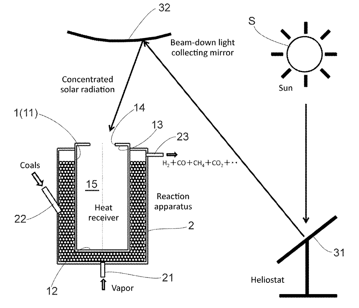
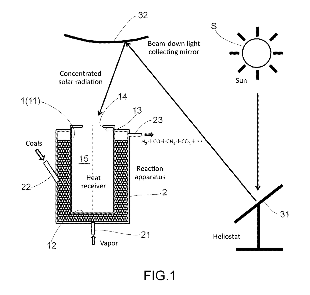
[0061]The reaction apparatus of concentrated solar radiation, as illustrated in FIG. 1 of the present embodiment, is a production system of hydrogen or the like by means of thermal decomposition of coke. Numeral 1 denotes a heat receiver made of a heat resisting material having high solar light absorptivity, such as Inconel, alumina, silicon carbide, stainless steel or the like. The heat receiver 1 includes a side portion 11 forming a cylindrical lateral face; a circular bottom portion 12 connected to a lower end of the side portion 11 to form a base of the heat receiver 1; and a ceiling 13 connected to an upper end of the side portion 11 to form a ceiling plane of the heat receiver 1. Further, through the center of the ceiling 13 is bored a circular aperture 14. That is, the heat receiver1 has a cylindrical profile with a cylindrical cavity 15 having an aperture 14 bored through to the inside. Note that the aperture 14 is provided with nothing at all, and the cavity 15 is in commun...

second embodiment

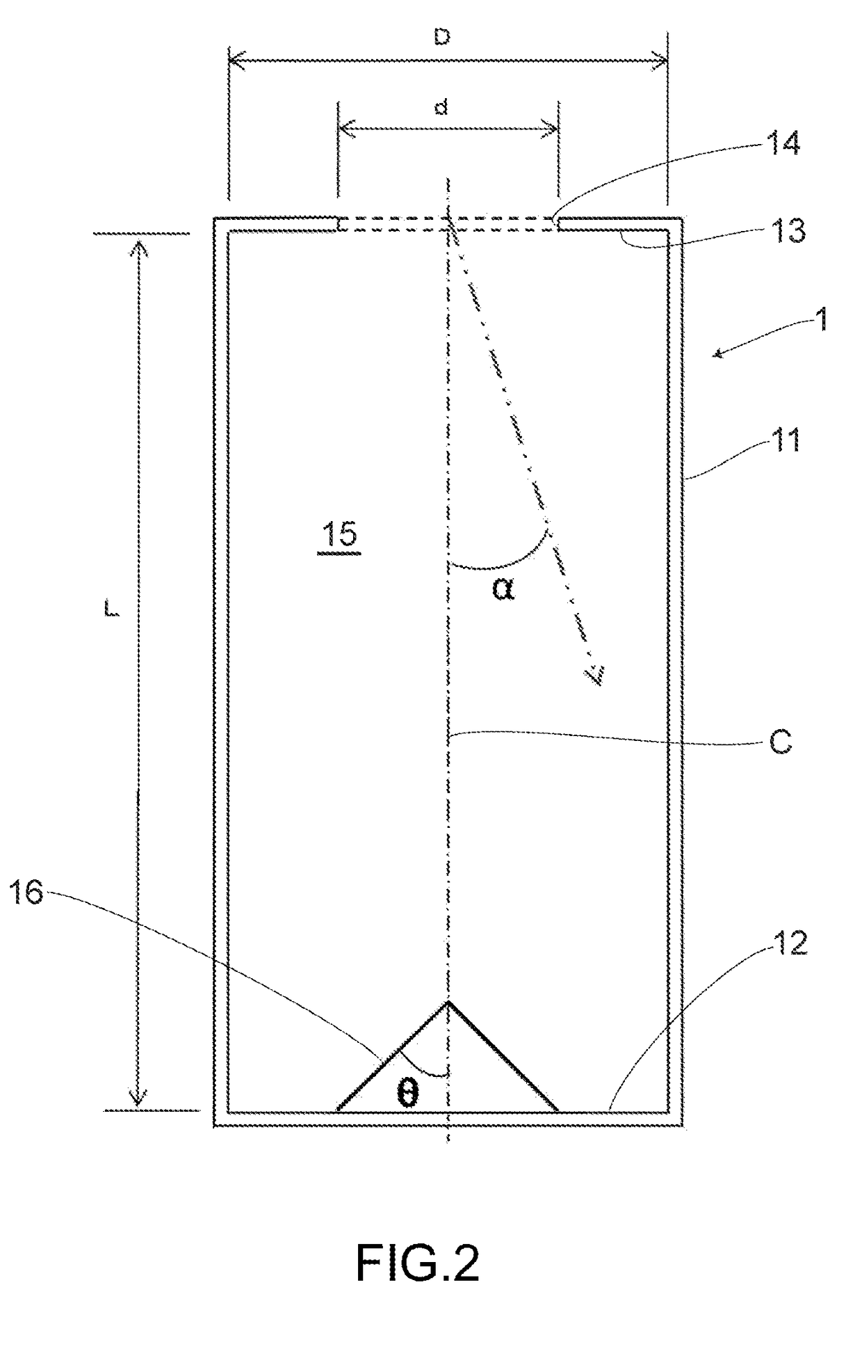
[0074]In an embodiment as illustrated in FIG. 3, a concentrated solar radiation, irradiated with a small angle α with respect to the central line C of the heat receiver 1, is to be ejected out of the heat receiver 1 with a small number of reflection. Due to this feature, in an embodiment as illustrated in FIG. 4, there is arranged a conical reflector 16 in a central portion of the bottom portion 12 of the heat receiver 1. It is preferred that the reflector 16 be conically shaped, having a diameter not smaller than d and that an elevation angle θ with respect to the central line C of the heat receiver 1 be in a range of 30 to 60 degrees.

[0075]As described above, there is arranged the conical reflector 16 in a central portion of the bottom portion 12, and the reflector 16 has a diameter not smaller than d and an elevation angle θ with respect to the central line C of the cavity 15 is in the range of 30° to 60° degrees. This concentrated solar radiation irradiated with a small angle α ...

third embodiment

[0076]According to an embodiment as illustrated in FIG. 5, in order to smooth out the irradiation intensity of the solar light onto the inner wall of the heat receiver 1, on a bottom portion of the heat receiver 1 is concentrically arranged two circular reflectors 17 having triangular cross sections. By suitably setting the elevation angles θ of the reflectors 17, with respect to the central line C of the heat receiver 1, and properly setting the number of the reflectors 17, solar lights are uniformly reflected by the inner wall of the heat receiver 1.

[0077]According to the first and second embodiments, the reflectors 16 and 17 has a convex outer surface although a reflector having a concave outer surface may be arranged on the bottom portion 12 of the heat receiver 1. If the reflector has a concave outer surface, the number of reflection that the solar light is reflected thereby until the solar light reaches to the side wall is large. Owing to this feature, it is preferred that the...


PUM


Abstract

A heat receiver, a reactor, and a heater utilize the heat of concentrated solar light for thermal decomposition and/or chemical reaction of coals, etc. The heat receiver includes: a side portion forming a substantially cylindrical side surface; a substantially circular bottom portion connected to the lower edge of the side portion; and a ceiling connected to the upper edge of the side portion. A substantially circular aperture is formed in the center of the ceiling. The heat receiver has a substantially cylindrical cavity and the opening portion is open. When the cavity has a diameter of D and a length of L, and the aperture has a diameter of d, d=D/2 or less and L=2D or more. Concentrated solar light entering the heat receiver is to be contained in the heat receiver to effectively utilize the solar light.

Description

CROSS-REFERENCE TO RELATED PATENT APPLICATIONS[0001]This application is a U.S. National Phase application under 35 U.S.C. §371 of International Patent Application No. PCT / JP2015 / 062332, filed Apr. 23, 2015, and claims the benefit of Japanese Patent Applications No. 2014-099859, filed May 13, 2014, all of which are incorporated by reference herein in their entireties. The International application was published in Japanese on Nov. 19, 2015 as International Publication No. WO / 2015 / 174236 under PCT Article 21(2).FIELD OF THE INVENTION[0002]The present invention relates to a heat receiver, a reactor and a heating apparatus of concentrated solar radiation.BACKGROUND OF THE INVENTION[0003]Fossil fuels such as petroleum, natural gas, coals (particularly bituminous) and nuclear energy source (which are sometimes categorized as fossil fuels) have been heretofore utilized as energy sources. Additionally, global population growth and industrial progress have led to a rapid growth in energy con...

Claims


Application Information

Patent Timeline
IPC IPC(8): C10J3/20C10B23/00F24S20/30F24S23/00
CPCC10J3/20C10B23/00C10J2300/093C10J2300/0916C10J2300/1284Y02E10/46Y02E70/30F03G6/06F03G6/067F28D20/0056F24S20/20F24S2010/751F24S2023/88F24S23/75F24S2080/05B01J8/1836B01J8/388B01J8/0055B01J8/006B01J8/0257B01J8/0285B01J2208/00451B01J2219/00247F24S60/20Y02E60/14Y02P20/133Y02E10/40F03G6/063
Inventor KODAMA, TATSUYAMATSUBARA, KOJIGOKON, NOBUYUKI
Owner NIIGATA UNIVERSITY
Why Eureka
Try Eureka