Wireless power transfer system

a power transfer system and wireless technology, applied in the direction of instruments, measurement devices, electrical apparatus, etc., can solve the problems of large heat generation in the driven primary coil, difficult to simultaneously achieve the optimal values of the respective parameters, and difficult to achieve high efficiency, stability, reliability, etc., and achieve simple circuit configuration and improved reliability.

Active Publication Date: 2017-05-25
WQC INC
View PDF0 Cites 19 Cited by
  • Summary
  • Abstract
  • Description
  • Claims
  • Application Information

AI Technical Summary

Benefits of technology

[0041]Further, being not bound by a resonance frequency of the primary coil, it is possible to automatically select, as a driving frequency, a frequency with the best power factor as seen from the primary coil side so that the robustness is largely improved.
[0042]Further, in the pres

Problems solved by technology

Further, it can be said that since there are many variable magnetic parameters in terms of constituent electronic circuits, it is very difficult to simultaneously achieve high efficiency, stability, reliability, and so on in the wireless power transfer.
Accordingly, even if an attempt is made to obtain optimal values of parameters of components of a driving circuit, values of the respective parameters do not necessarily cooperate with each other and are often in a trade-off relationship to conflict with each other, and therefore, it is extremely difficult to simultaneously achieve optimal values of the respective parameters.
Currentl

Method used


Image

  • Wireless power transfer system
  • Wireless power transfer system
  • Wireless power transfer system

Examples


Embodiment Construction

[0068]Hereinbelow, an aspect of a wireless power transfer system according to the presently disclosed embodiment will be described in detail with reference to the accompanying drawings.

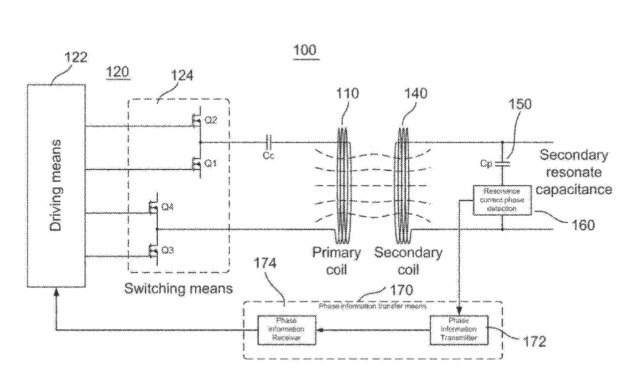
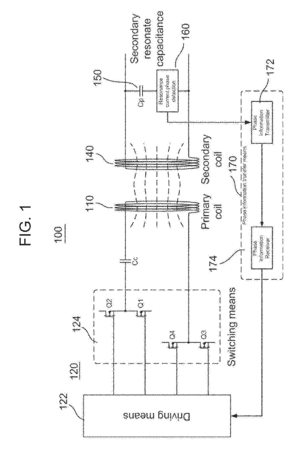
[0069]FIG. 1 is a block diagram showing a configuration of a main part of one aspect of a wireless power transfer system 100 according to the presently disclosed embodiment.

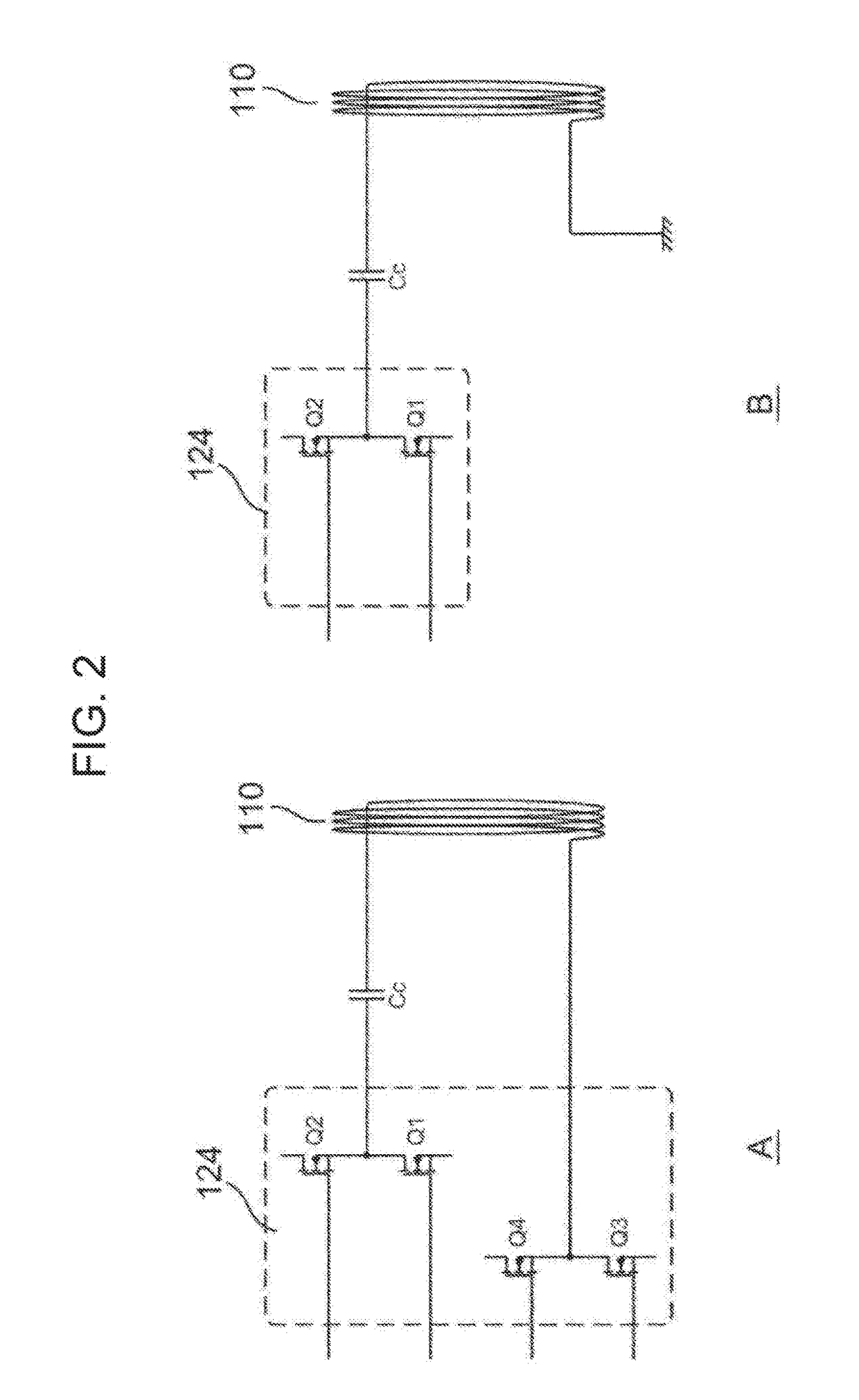
[0070]The primary side includes a primary coil (Primary coil) 110 and a driving circuit 120 connected to the primary coil 110 via a capacitor Cc. The driving circuit 120 includes a driving means (Driving means) 122 and a switching means (Switching means) 124. The switching means 124 is formed as a bridge circuit including transistor elements Q1 to Q4.

[0071]The secondary side includes a secondary coil (Secondary coil) 140 disposed so as to be isolated from the primary coil 110 with a coupling coefficient k, a resonance capacitor (Cp) 150 connected to the secondary coil 140 to form a resonance circuit, and a resonance current phase d...


PUM


Abstract

In a wireless power transfer system, a resonant circuit is formed on the secondary coil side, phase information of a resonant current flowing in the resonant circuit is detected, and, based on this phase information, a driving frequency is determined so that the current phase of a driving current flowing in a primary coil slightly delays from the voltage phase, thereby driving the primary coil. A Q valued determined based on a leakage inductance of the secondary coil, a capacitance of a resonant capacitor, and an equivalent load resistance is set to a value greater than or equal to a value determined by Q=2/k2 (k is a coupling coefficient).

Description

CROSS REFERENCE TO RELATED APPLICATIONS[0001]This application is the National Stage of International Application No. PCT / JP2014 / 004827 having an International Filing Date of 19 Sep. 2014, which designated the United States of America, and which International Application was published under PCT Article 21 (2) as WO Publication 2015 / 173850 A1, and which claims priority from and the benefit of International Application No. PCT / JP2014 / 002552, filed on 14 May 2014, the disclosures of which are incorporated herein by reference in their entireties.DESCRIPTION[0002]1. Field[0003]The presently disclosed embodiment relates to a wireless power transfer system and, in particular, relates to a wireless power transfer system in which a primary coil connected to a high-frequency power source and a secondary coil connected to a load are disposed so as to be isolated from each other with a coupling coefficient k, thereby supplying the power from the primary coil to the secondary coil in a non-contac...

Claims


Application Information

Patent Timeline
IPC IPC(8): H02J50/12H02J50/90
CPCH02J50/90H02J50/12H02J50/80G01R25/005
Inventor USHIJIMAYUASA, HAJIMEOGINO, GO
Owner WQC INC
Why Eureka
Try Eureka