Piezoelectric element and bend detecting sensor

a technology of bend detection and piezoelectric element, which is applied in the field of piezoelectric elements, can solve the problems of difficult to precisely detect the output the voltage of the piezoelectric element is significantly influenced by, and the voltage produced in the piezoelectric element becomes too high

Active Publication Date: 2017-06-08
MURATA MFG CO LTD
View PDF0 Cites 6 Cited by
  • Summary
  • Abstract
  • Description
  • Claims
  • Application Information

AI Technical Summary

Benefits of technology

[0015]The polylactic acid does not produce pyroelectricity unlike the ferroelectric material such as PVDF. Further, the polylactic acid does not need to be poled (polarization processing) and has light-transmissiveness, and therefore is better than PVDF.

Problems solved by technology

When the piezoelectric element disclosed in the foregoing application is directly connected to a voltage detection circuit, the causes following problems to occur.
First, a voltage produced in the piezoelectric element becomes too high, and when, for example, it exceeds a drive voltage of the voltage detection circuit, it is difficult to precisely detect an output voltage from the piezoelectric element.
Second, because a capacitance of the piezoelectric element is low, the voltage of the piezoelectric element is significantly influenced by noise superimposed on the charges generated by the piezoelectric film.
Third, because the capacitance of the piezoelectric element is low, a time constant becomes low and the charges quickly dissipate from the piezoelectric element.

Method used


Image

  • Piezoelectric element and bend detecting sensor
  • Piezoelectric element and bend detecting sensor
  • Piezoelectric element and bend detecting sensor

Examples


first embodiment

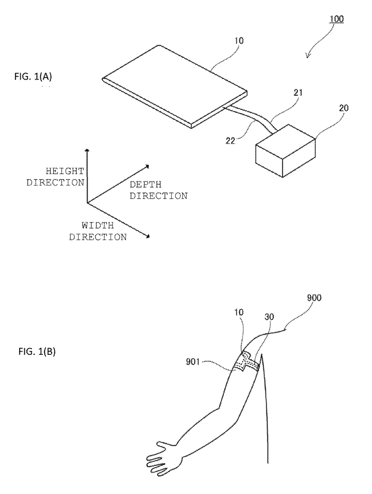
[0034]A biosensor 100 will be described with reference to FIGS. 1(A), 1(B) and 2. The biosensor 100 is typically attached to the surface of the skin of a living body to detect a displacement of the skin surface.

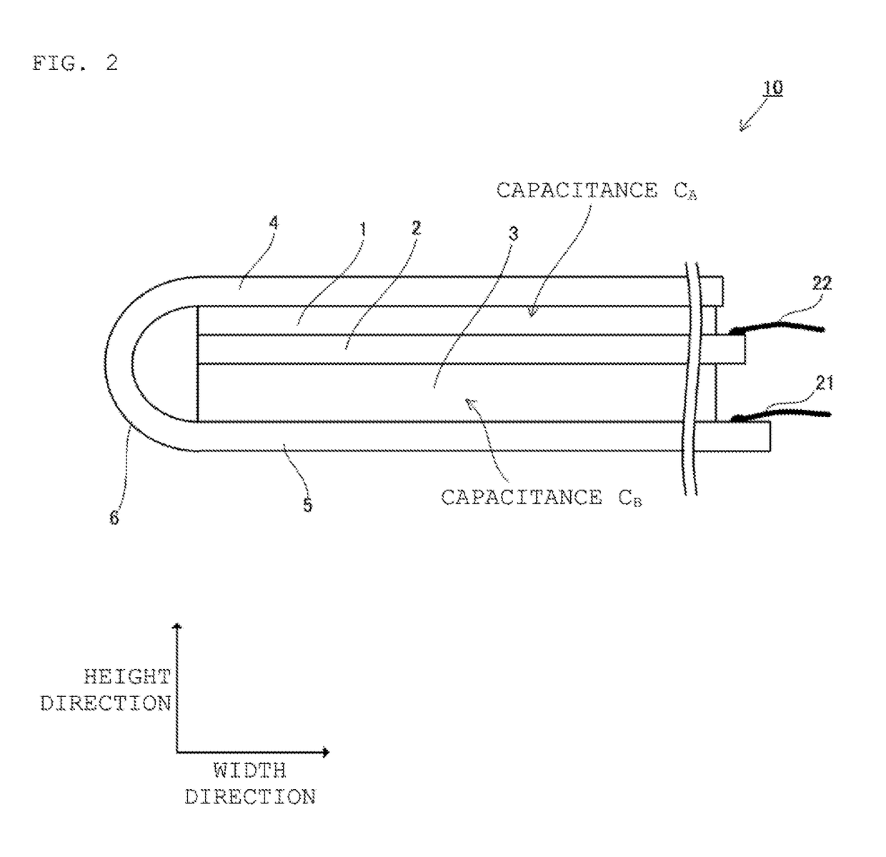
[0035]As illustrated in FIG. 1(A), the biosensor 100 includes the sensor element 10 and a detecting unit 20. The sensor element 10 and the detecting unit 20 are electrically connected with signal lines 21 and 22 interposed therebetween. Alternatively, the detecting unit 20 may be directly connected to the sensor element 10 without the use of signal lines. The sensor element 10 has a film shape which is thin in a height direction as compared to a width and depth directions.

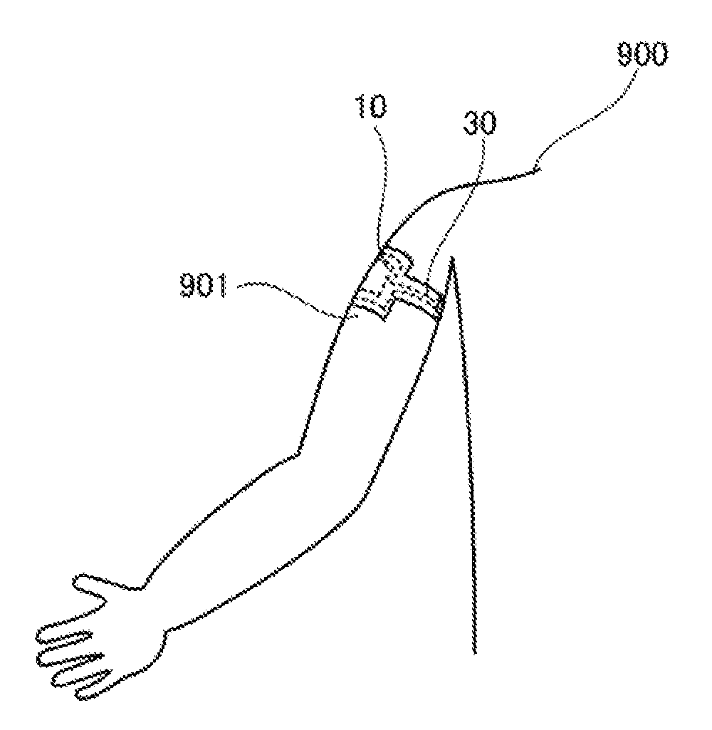
[0036]As illustrated in FIG. 1(B), the biosensor 100 is attached to a living body 900 such that an upper surface (a surface in the height direction as viewed in FIG. 1(A)) or a lower surface (a surface in a direction opposite to the height direction as viewed in FIG. 1(A))) of the sensor element 10 comes in...

second embodiment

[0064]Next, a sensor element 10A will be described with reference to FIGS. 4, 5(A), and 5(B). FIG. 4 is a side view illustrating the sensor element 10A seen from a depth direction. FIG. 5(A) is a top view of a piezoelectric film 31 (corresponding to a first film), and FIG. 5(B) is a top view of a piezoelectric film (corresponding to a second film).

[0065]The sensor element 10A does not produce charges when stretched or contracted in a planar direction (a width direction and the depth direction), and produces charges only when curved in a laminating direction. More specifically, the sensor element 10A differs from a sensor element 10 in that a piezoelectric film 3A is formed by two piezoelectric film layers 31 and 32.

[0066]The piezoelectric films 31 and 32 are made of polylactic acid having different compositions. The piezoelectric film 31 is preferably made of Poly-D-Lactic-Acid (PDLA), and the piezoelectric film 32 is preferably made of Poly-L-Lactic-Acid (PLLA). The order of those...

third embodiment

[0077]FIG. 7 is a side view of a sensor element 10B seen from a depth direction. FIG. 8 is a top view of a piezoelectric film 31B.

[0078]The sensor element 10B differs from the sensor element 10 in that it includes the piezoelectric film 31B instead of the piezoelectric film 31. Components which overlap with components of the sensor element 10 will not be described.

[0079]The piezoelectric film 31B is preferably made of PLLA. The piezoelectric film 31B is stretched in a clockwise direction by 45° with respect to a width direction as indicated by an outlined arrow 913 in FIG. 8. Thus, the PLLA included in the piezoelectric film 31B is oriented in the clockwise direction by 45° from the width direction. Hence, the piezoelectric film 31B and a piezoelectric film 32 have orientation directions of molecules of polylactic acid which are orthogonal to each other and are made of the same composition, and therefore have reverse charge directions.

[0080]In this regard, the sensor element 10B in...


PUM


Abstract

A capacitor is coupled in parallel with a piezoelectric unit in a sensor. The piezoelectric unit is formed by a film which is sandwiched between a signal electrode and a reference potential electrode. A capacitor is formed by a dielectric film located between the signal electrode and a reference potential electrode. As a result, the capacitance of the sensor element is higher than it would be if the sensor only contained the piezoelectric unit.

Description

CROSS REFERENCE TO RELATED APPLICATIONS[0001]The present application is a continuation of International application No. PCT / JP2015 / 071060, filed on Jul. 24, 2015, which claims priority to Japanese Patent Application No. 2014-165887, filed on Aug. 18, 2014, the entire contents of each of which are incorporated herein by reference.TECHNICAL FIELD[0002]The present invention relates to a piezoelectric element which includes a film partially including a piezoelectric resin and sandwiched between electrodes.BACKGROUND ART[0003]In recent years, piezoelectric elements which each include a film (simply referred to as a piezoelectric film below) partially including, for example, polyvinylidene fluoride as piezoelectric resin and sandwiched between electrodes are known. For example, Japanese Patent Application Laid-Open No. H06-216422 discloses a piezoelectric element formed by disposing piezoelectric films made of polyvinylidene fluoride on opposite principal surfaces of electrodes, disposing...

Claims


Application Information

Patent Timeline
Patent Type & Authority Applications(United States)
IPC IPC(8): A61B5/11A61B5/00H01L41/113H01L41/193H01L41/08G01B7/16H01L41/047
CPCA61B5/11G01B7/22A61B5/6831H01L41/1132H01L41/0477H01L41/193H01L41/0805A61B5/6824G01L1/16A61B5/1126A61B2562/0261H10N30/802H10N30/877H10N30/302H10N30/857H10N30/1051
Inventor KAWAMURA, HIDEKI
Owner MURATA MFG CO LTD
Why Eureka
Try Eureka