
Battery cooling system for a vehicle

a battery cooling and vehicle technology, applied in the field of vehicle battery cooling system, can solve the problems of increasing the size and weight of the battery cooling module provided in the front side of the vehicle, the complex layout of the connection pipe through which a refrigerant or cooling water is supplied to the heat pump system, and the battery cooling system respectively in the engine compartment becomes complex, so as to improve the overall travel distance of the vehicle, improve the efficiency of battery management, and simplify the system

Inactive Publication Date: 2017-06-08
HYUNDAI MOTOR CO LTD
View PDF3 Cites 47 Cited by
  • Summary
  • Abstract
  • Description
  • Claims
  • Application Information

AI Technical Summary

Benefits of technology

The present invention is a battery cooling system for vehicles that uses a refrigerant and cooling water to warm up or cool down the battery module. The system is designed to increase the travel distance of the vehicle and manage the battery in a more efficient way. By simplifying the system and reducing the number of valves, manufacturing costs and weight can be reduced, and riding comfort can be improved. The technical effects of the invention include increased travel distance, simplified system design, reduced manufacturing costs, and improved riding comfort.

Problems solved by technology

Thus, the size and weight of a cooling module provided in the front side of the vehicle increase, and a layout of connection pipe through which a refrigerant or cooling water is supplied to the heat pump system, the electric unit cooling device, and the battery cooling system respectively in an engine compartment becomes complex.
Further, since the battery cooling system that warms up or cools down the battery based on a vehicle state for optimal performance of the battery is provided separately, a plurality of valves are required to connect the battery cooling system to the respective connection pipes and noise and vibration generated from frequent closing and opening of the valves are transferred to the interior of the vehicle, thereby deteriorating riding comfort.

Method used


Image

  • Battery cooling system for a vehicle
  • Battery cooling system for a vehicle
  • Battery cooling system for a vehicle

Examples


Embodiment Construction

[0051]It is understood that the term “vehicle” or “vehicular” or other similar term as used herein is inclusive of motor vehicles in general such as passenger automobiles including sports utility vehicles (SUV), buses, trucks, various commercial vehicles, watercraft including a variety of boats and ships, aircraft, and the like, and includes hybrid vehicles, electric vehicles, plug-in hybrid electric vehicles, hydrogen-powered vehicles and other alternative fuel vehicles (e.g. fuels derived from resources other than petroleum). As referred to herein, a hybrid vehicle is a vehicle that has two or more sources of power, for example both gasoline-powered and electric-powered vehicles.

[0052]Although exemplary embodiment is described as using a plurality of units to perform the exemplary process, it is understood that the exemplary processes may also be performed by one or plurality of modules. Additionally, it is understood that the term controller / control unit refers to a hardware devi...


PUM


Abstract

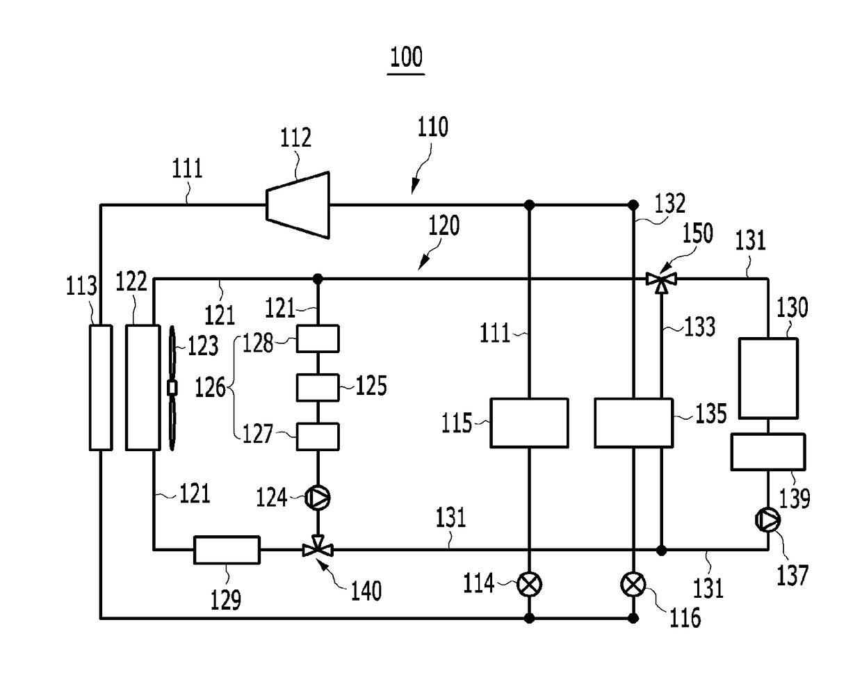
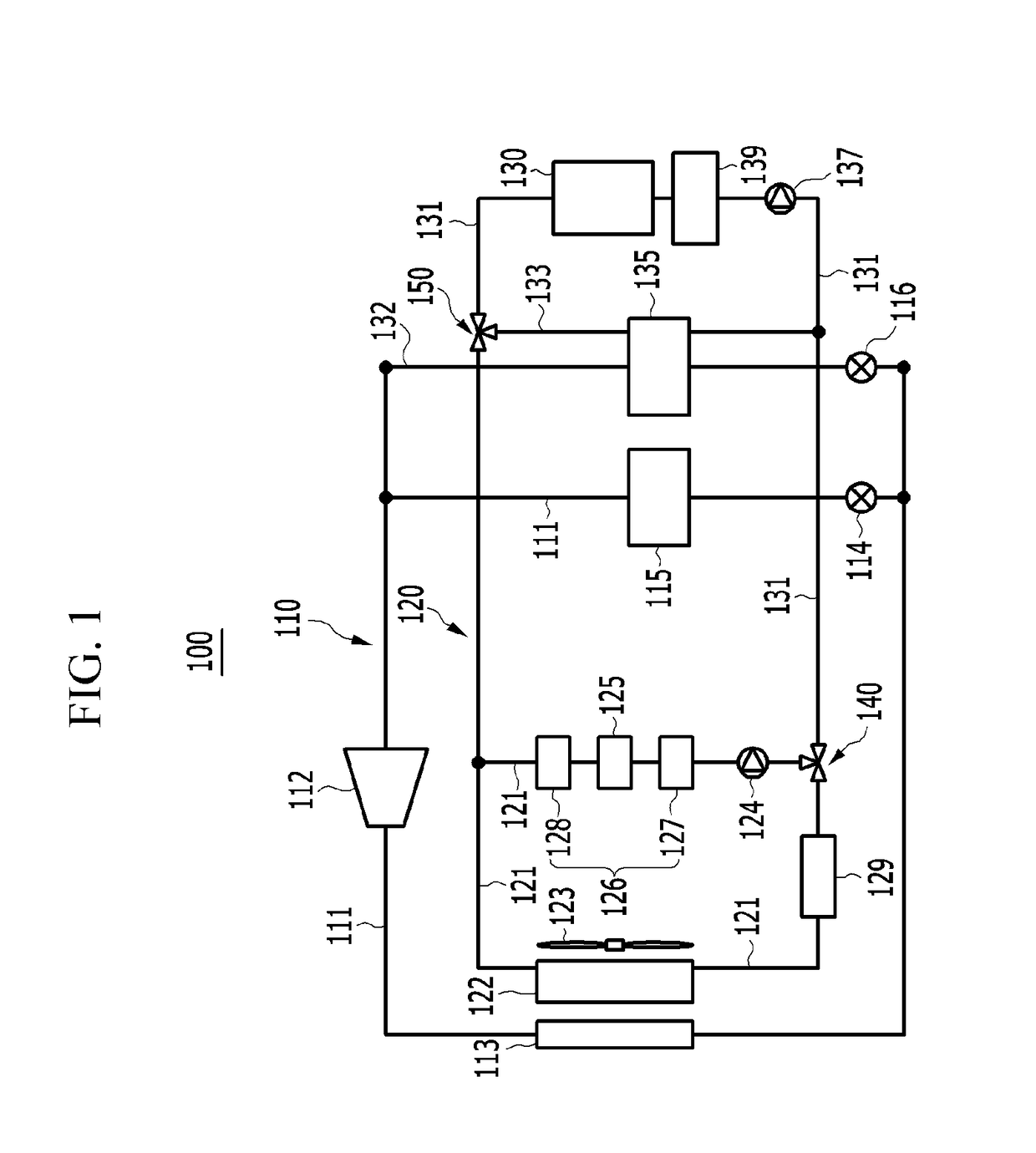
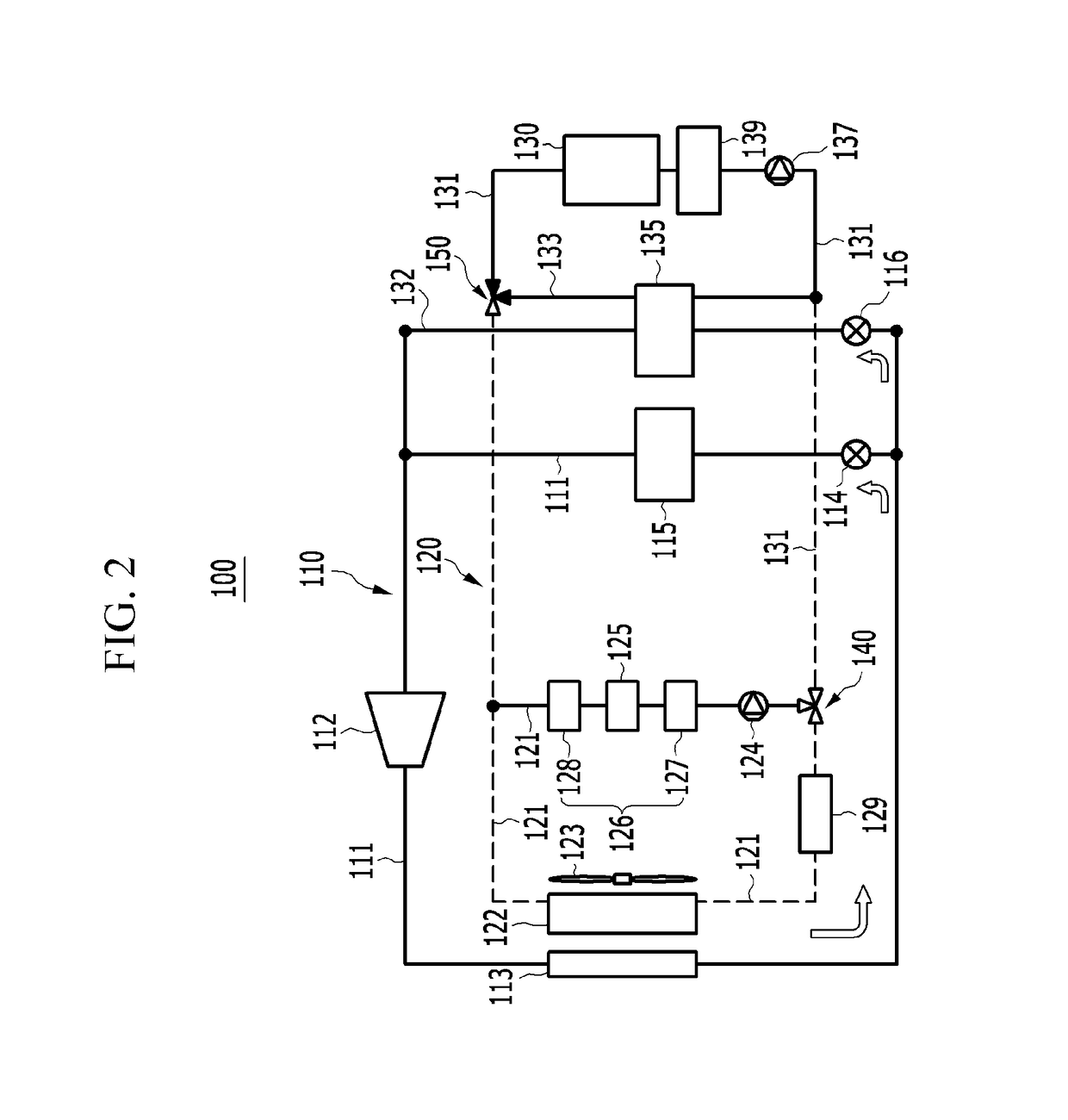
A vehicle battery cooling system is provided and includes an air conditioning device including a compressor, condenser, evaporator, and first expansion valve connected via a refrigerant line and circulates refrigerant to reduce temperature within the vehicle. An electric unit cooling device includes an electric unit radiator and water pump connected with a cooling line and circulates cooling water to cool a motor and electric unit. A battery module connects with the cooling device via a battery cooling line. A chiller connects with the refrigerant line via a first connection line and the battery cooling line via a second connection line, and adjusts cooling water temperature by selectively heat-exchanging cooling water and refrigerant. Another water pump is disposed on the battery cooling line between the battery module and the chiller and a heater is disposed on the battery cooling line between the other water pump and the battery module.

Description

CROSS-REFERENCE TO RELATED APPLICATION[0001]This application claims priority to and the benefit of Korean Patent Application No. 10-2015-0174241 filed in the Korean Intellectual Property Office on Dec. 8, 2015, the entire contents of which are incorporated herein by reference.BACKGROUND[0002](a) Field of the Invention[0003]The present invention relates to a battery cooling system for a vehicle, and more particularly, to a battery cooling system for a vehicle, that interlocks an air conditioning device and an electric unit cooling device that circulates cooling water in a motor and an electric unit within an electric vehicle or a hybrid vehicle and warms up or cools down a battery module based on a vehicle state using the cooling water circulating the electric unit cooling device.[0004](b) Description of the Related Art[0005]In general, an air conditioning system for a vehicle includes an air conditioning system that circulates a refrigerant to warm up or cool down the interior of th...

Claims


Application Information

Patent Timeline
IPC IPC(8): B60L11/18H01M10/625H01M10/663B60H1/00H01M10/63H01M10/615H01M10/617H01M10/613H01M10/6568
CPCB60L11/1874H01M10/613H01M10/625H01M10/663H01M10/6568H01M2220/20H01M10/615H01M10/617B60H1/00278B60L11/1875H01M10/63B60L58/26F25D1/02F25B2341/06F25B41/20B60H1/323B60H2001/00307B60L58/27B60H1/32281Y02T10/70Y02E60/10Y02T10/7072Y02T90/12
Inventor KIM, JAE YEONKIM, MYUNGHWANWOO, JEONG YEOPKIM, YEON HOCHO, WAN JELEE, GUN GOO
Owner HYUNDAI MOTOR CO LTD
Learn More