
Capacitance measurement in a bearing

a technology of capacitance measurement and bearing, which is applied in the direction of mechanical equipment, rotary machine parts, instruments, etc., can solve the problems of hydrogen embrittlement, surface erosion and cavitation of bearings, and failure of bearings

Active Publication Date: 2017-06-08
AB SKF
View PDF1 Cites 4 Cited by
  • Summary
  • Abstract
  • Description
  • Claims
  • Application Information

AI Technical Summary

Benefits of technology

The goal of this patent is to create a better bearing that can be easily monitored to prevent unexpected failures. This will improve the reliability and durability of bearings in various applications.

Problems solved by technology

It has been found that bearing failures are often caused by water in the bearing lubricant.
Water in the lubricant can cause surface erosion and cavitations within the bearing.
Also, it can cause hydrogen embrittlement due to the extreme pressures in rolling element bearings, which can be as high as 1 to 3 GPa, where water can break down into its constituent atoms causing hydrogen to penetrate the surface of the bearing elements and cause the surface to become more brittle.
Water can also cause additives to precipitate and cause abrasive particles or sludge to form.
Water also causes the base oil to oxidize much more quickly.
For example, a bearing exposed to the elements (such as a wheel bearing on a train or car) is more susceptible to contamination, both by water and by other contaminating particles.
Although the monitoring that is currently described in the art helps the scheduling of maintenance and prediction of failures before they occur, and thereby may improve the availability of rotating systems, many such systems are both complicated and impractical to use in many applications.

Method used


Image

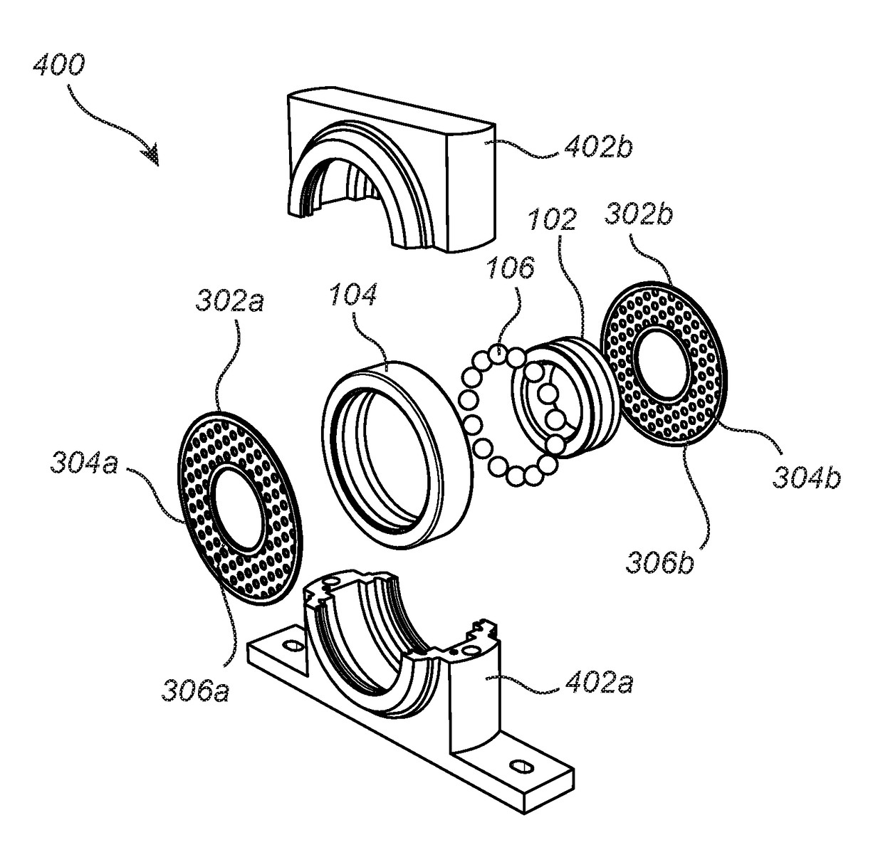
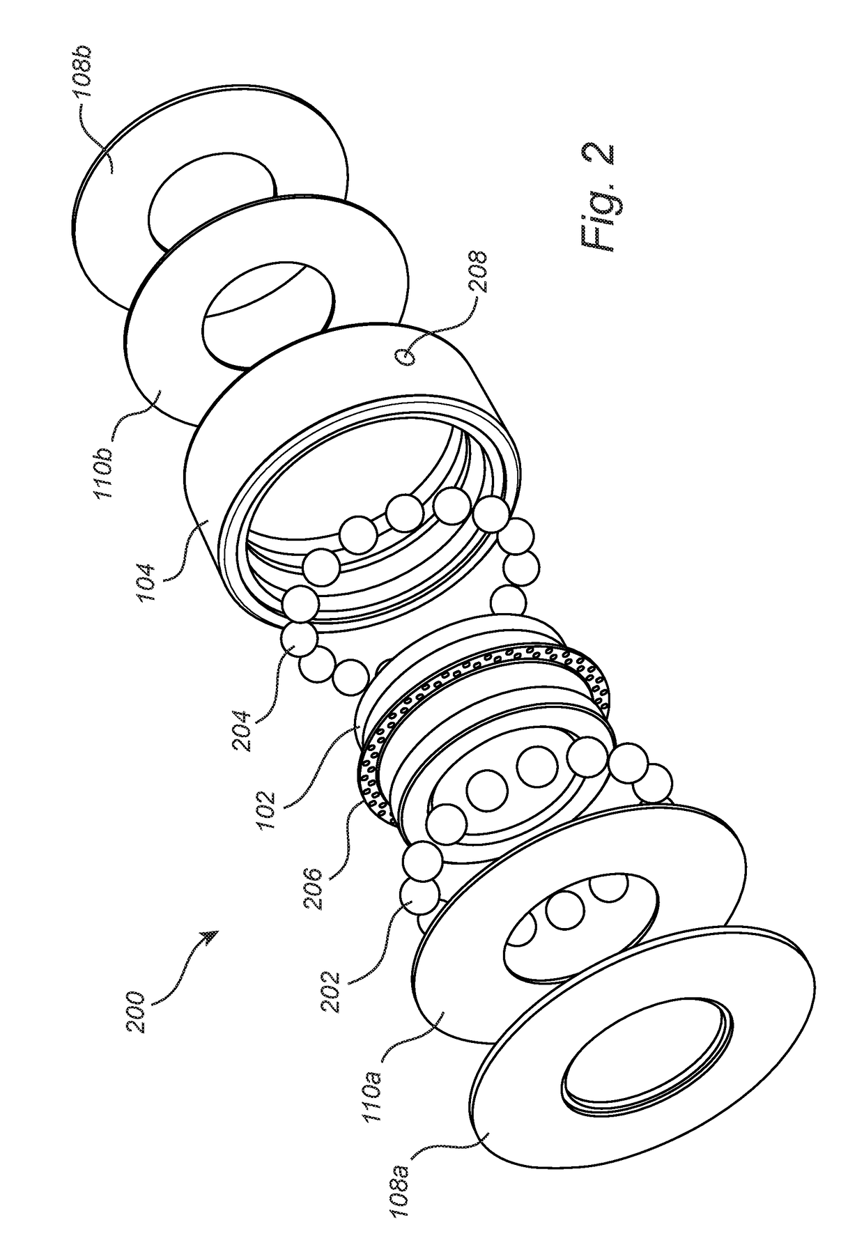
  • Capacitance measurement in a bearing
  • Capacitance measurement in a bearing
  • Capacitance measurement in a bearing

Examples


Embodiment Construction

[0036]In the present detailed description, various embodiments of bearing arrangement according to the present invention are mainly discussed with reference to a ball bearing. It should be noted that this by no means limits the scope of the present invention which is equally applicable to any type of bearing comprising a lubricant.

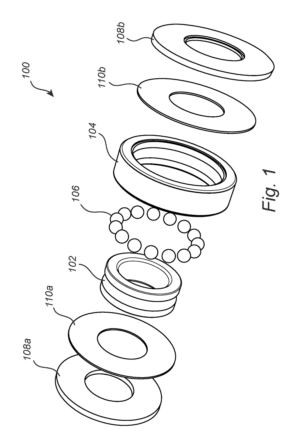
[0037]FIG. 1 is an exploded view of a bearing 100 comprising an inner race 102, an outer race 104 and a plurality of rolling elements 106 in the form of balls arranged between the inner and outer race. The bearing further provides sealing rings 108a-b arranged on the respective sides of the bearing to seal the bearing. Herein, both the sealing rings 108a-b and the races 102,104 are made from a conductive material. Furthermore, electrically insulating frames 110a-b are arranged to electrically insulate the sealing rings 108a-b from the races 102,104. A lubricant (not shown) is arranged within the bearing to provide lubrication for the rolling elements 106. ...


PUM


Abstract

A bearing arrangement includes a bearing having an inner race and an outer race and a plurality of rolling elements arranged between the inner and outer race such that the first race is rotatable relative the second race; bearing lubricant arranged within the bearing to lubricate the rolling elements. The bearing arrangement provides a first electrically conductive portion and a second electrically conductive portion, the first and second electrically conductive portion being electrically insulated and arranged such that at least a portion of the bearing lubricant is located between the first and second electrically conductive portion; and a capacitance meter having a first electrode connected to the first electrically conductive portion and a second electrode connected to the second electrically conductive portion, configured to measure a capacitance between the first ring and the second ring to determine a water content in the lubricant based on the measured capacitance.

Description

CROSS REFERENCE TO RELATED APPLICATIONS[0001]This is a United States National Stage Application claiming the benefit of International Application Number PCT / SE2015 / 050544 filed on 05.13.2015, which claims the benefit of Sweden Patent Application 1450586-1 filed on 05.19.2014, both of which are incorporated herein by reference in their entireties.FIELD OF THE INVENTION[0002]The present invention relates to a bearing arrangement. In particular, the present invention relates to a bearing comprising a capacitance sensor for determining a characteristic of a lubricant in the bearing.BACKGROUND OF THE INVENTION[0003]Bearings and in particular rolling bearings are used in a wide range of applications comprising rotating shafts. Rolling bearings provide low friction rotation by means of the rolling elements arranged between the outer and inner race of the bearing. To further reduce the friction between the rolling elements and the races, thereby increasing the life length of the bearing, a ...

Claims


Application Information

Patent Timeline
IPC IPC(8): F16C41/00G01N33/28G01M13/04G01N27/22F16C19/52F16C33/66
CPCF16C41/002F16C19/525F16C33/6688G01M13/04F16C2360/31G01N33/2847G01N33/2888F16C2233/00G01N27/223F16C19/52G01N33/30G01N27/226F16J15/324
Inventor DITTES, NICHOLAS
Owner AB SKF
Learn More