Continuous winding magnets using thin film conductors without resistive joints

a technology of conductors and magnets, applied in the direction of superconducting magnets/coils, magnets, magnetic bodies, etc., can solve the problems of complex metallurgy, performance degradation, and the need for expensive cryogenic equipment to manage the head load

Active Publication Date: 2017-06-08
UCHICAGO ARGONNE LLC
View PDF3 Cites 5 Cited by
  • Summary
  • Abstract
  • Description
  • Claims
  • Application Information

AI Technical Summary

Problems solved by technology

The wire technology of NbTi is highly developed; however, this material, which has comparatively low superconducting transition temperature of Tc˜10 K and upper critical field of 14 T, reaches its material limitations particularly in regards to the high-field critical current density at an operating temperature of 4.2 K, and further performance enhancements of SCU will require the use of different superconducting materials.
Even though Nb3Sn is a well-established material allowing for significantly enhanced performance as compared to NbTi, its metallurgy is complicated.
Dimensional deformations of the undulator core that can occur during this annealing step interfere with the need for very tight mechanical tolerances of the undulator, an issue that has not been resolved yet and also after high-temperature annealing step, wire becomes brittle which results in performance degradation.
Managing this head-load requires expensive cryogenic equipment for operating NbTi-undulators.
A possible drawback is that in the final conductor only roughly 1% of the cross-section is superconducting.
A major hurdle in realizing this potential arises from the difficulties in transferring well-established magnet technologies developed for Nb-based wires to the tape-shaped REBCO-conductors.
Therefore, the traditional layer-by-layer winding approach is, in most cases, not feasible with coated conductors, and HTS magnets are typically wound as a stack of so-called pancake coils.
Connecting the pancake coils to each other and to the current leads is challenging, and various schemes have been proposed.
However, this design did not perform well as compared to NbTi-based undulators since the achieved Je was only about 700 A / mm2.
A major drawback that is likely to prevent the scalability of this design to a full-scale undulator is the large number of soldered bridge joints, two per pancake coil.
In contrast to Nb-based superconductors, it is currently not possible to make truly superconducting joints between sections of coated conductors in the environments typical for coil winding; the soldered bridge joints are resistive.
A recently reported procedure for making superconducting joints requires delicate post-processing involving high-temperature post-annealing in oxygen and under pressure.
The localized heat generation may cause quenches of the superconductor nearby.
Furthermore, the mechanical stiffness of the joint is very different than that of the isolated coated conductor, which could cause damage due to differential thermal contraction on cool-down.

Method used


Image

  • Continuous winding magnets using thin film conductors without resistive joints
  • Continuous winding magnets using thin film conductors without resistive joints
  • Continuous winding magnets using thin film conductors without resistive joints

Examples


Embodiment Construction

[0019]In the following detailed description, reference is made to the accompanying drawings, which form a part hereof. In the drawings, similar symbols typically identify similar components, unless context dictates otherwise. The illustrative embodiments described in the detailed description, drawings, and claims are not meant to be limiting. Other embodiments may be utilized, and other changes may be made, without departing from the spirit or scope of the subject matter presented here. It will be readily understood that the aspects of the present disclosure, as generally described herein, and illustrated in the figures, can be arranged, substituted, combined, and designed in a wide variety of different configurations, all of which are explicitly contemplated and made part of this disclosure.

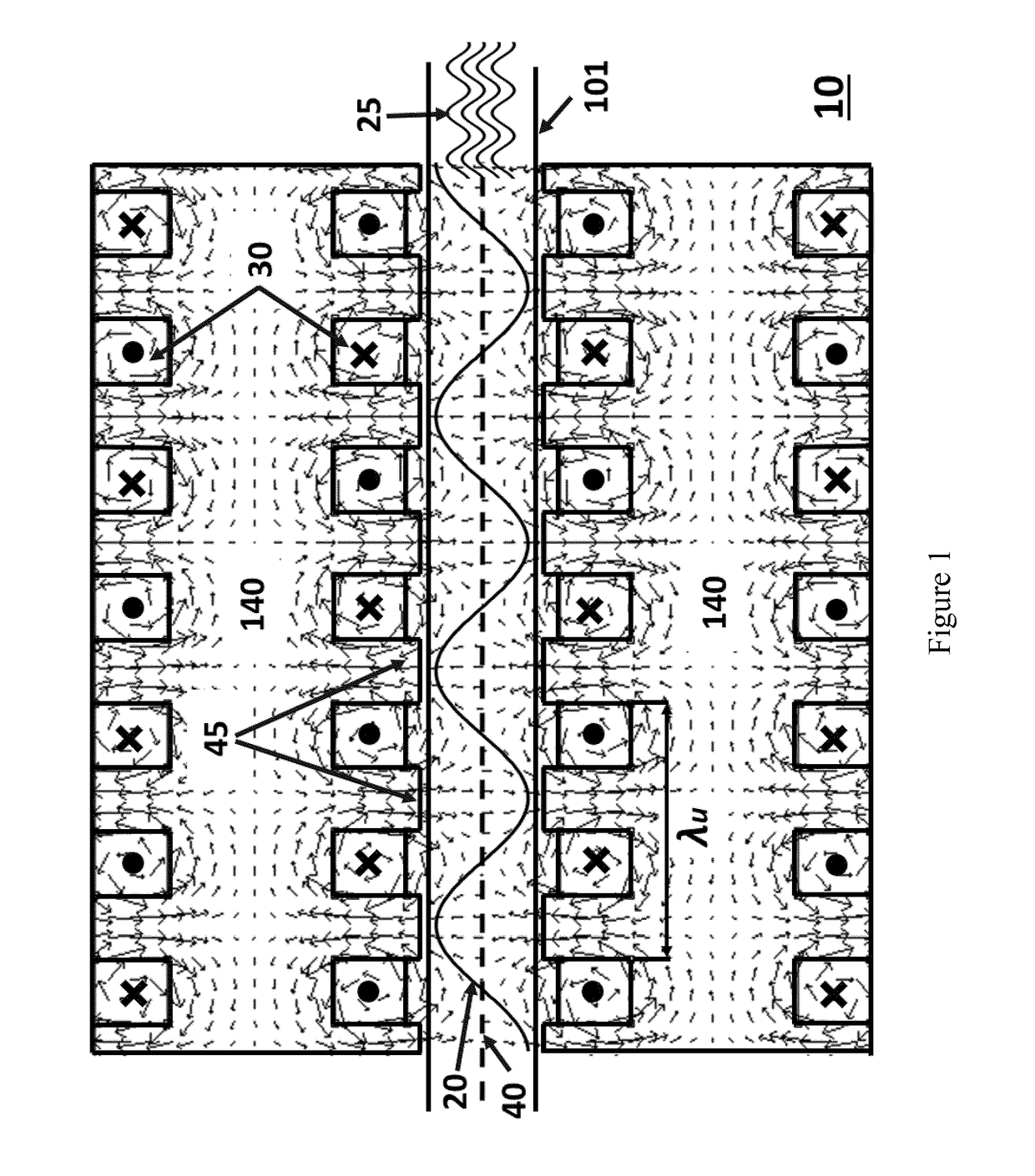
[0020]FIG. 1 shows the fundamental principle of an undulator 10 with its components. Only the parts that are closest to the electron beam 40 (dashed horizontal line) are shown for clarity. The m...


PUM

PropertyMeasurementUnit
Tcaaaaaaaaaa
Tcaaaaaaaaaa
temperatureaaaaaaaaaa

Abstract

A continuous winding method produces a continuously wound electrical device, such an undulator. A continuous tape is wound about a series of turn around pins and in grooves in a magnetic core. A plurality of winding stacks are created, each transitioning to the next sequential stack by a transition tape portion extending from one turn around pin to the next turn around pin, which is position opposite with regard to the location of the pin on the magnetic core.

Description

STATEMENT OF GOVERNMENT INTEREST[0001]The United States Government has rights in the invention described herein pursuant to Contract No. DE-AC02-06CH11357 between the United States Department of Energy and UChicago Argonne, LLC, as operator of Argonne National Laboratory.FIELD OF THE INVENTION[0002]The present invention generally relates to magnet windings, specifically to those made from high-temperature superconducting (HTS) coated conductors.BACKGROUND OF THE INVENTION[0003]This invention, in general, pertains to the fabrication of superconducting magnets utilizing thin film conductors. In particular, we describe and demonstrate a technique that allows for the continuous winding of undulator magnets using HTS Rare-Earth (RE) Barium Copper Oxide (REBCO) coated conductor tapes.[0004]The availability of powerful, partly coherent x-ray and deep UV beams has enabled tremendous advances in science and technology across a broad range of disciplines, including materials science, biology,...

Claims


Application Information

Patent Timeline
Patent Type & Authority Applications(United States)
IPC IPC(8): H01F6/06H01F7/02B65H18/02H01F1/04
CPCH01F6/06B65H18/021H01F7/021H01F1/04B65H18/106B65H18/28H01F41/048H05H7/04B65H2301/412845B65H2301/41398B65H2301/414321B65H2301/41461B65H2403/942H05H2007/041B65H2401/21
Inventor KESGIN, IBRAHIMWELP, ULRICHDOOSE, CHARLES L.KASA, MATTHEWIVANYUSHENKOV, YURY
Owner UCHICAGO ARGONNE LLC
Why Eureka
Try Eureka