Wheel Deburring Device

a deburring device and wheel technology, applied in the field of deburring devices, can solve the problems of poor burr processing effect on the roots of the ring flange of the wheel, low efficiency, and inability to meet the ideal requirements of burr processing on the rim corners, etc., to achieve advanced technology, simple structure, and high degree of automation.

Active Publication Date: 2017-06-29
CITIC DICASTAL
View PDF11 Cites 19 Cited by
  • Summary
  • Abstract
  • Description
  • Claims
  • Application Information

AI Technical Summary

Benefits of technology

[0004]An object of the present invention is to provide a wheel deburring device which can be used for carrying out focused processing on burrs of root corners of flanges and burrs of root corners of rims of wheels.
[0010]When in use, the wheel deburring device can be used for carrying out focused processing on the burrs of the root corners of the flanges and the burrs of the root corners of the rims of the wheels, so that the problem of the traditional large-disc brushes that the burr processing effect on flange corner positions is poor due to the fact that the linear velocity of a position close to a central position is low when an angular velocity is definite is completely avoided. The problem of the traditional large-disc brushes that the burr processing effect on wheel rim corner positions is poor due to the fact that edge brush hairs of the traditional large-disc brushes are hardly made into shapes which are completely consistent with those of rim corners of wheels is also avoided. At the same time, the wheel deburring device has the characteristics of simple structure, high degree of automation, advanced technology, high universality, high efficiency and safe and stable performance.

Problems solved by technology

At present, a deburring mode for wheel industry is that two large-disc brushes, i.e., an upper large-disc brush and a lower large-disc brush are used for brushing burrs of a back cavity and a front surface of a wheel, in this mode, when angles of the brushes are definite, the lower the linear velocity for brush hairs, the closer the brush central position, so that the problem that the burr processing effect on roots of ring flanges of wheels is poor is directly caused.
Edge brush hairs of the traditional large-disc brushes are hardly made into shapes which are completely consistent with those of rim corners of the wheels, so that the problem that the burr processing effect on the rim corners often does not meet the ideal requirements is caused.
At the above two positions, a great deal of labor is required to be input so as to carry out manual grinding, the efficiency is low, the cost is high, and the effect is non-uniform, so that the wheel deburring device is used for carrying out focused processing on burrs of root corners of flanges, thus, the labor intensity for grinders is lowered, and the production efficiency is increased.

Method used


Image

  • Wheel Deburring Device
  • Wheel Deburring Device
  • Wheel Deburring Device

Examples


Embodiment Construction

[0016]In the following, the details and working conditions of a specific device provided by the present invention are described in combination with the figures.

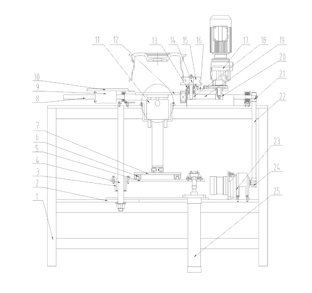
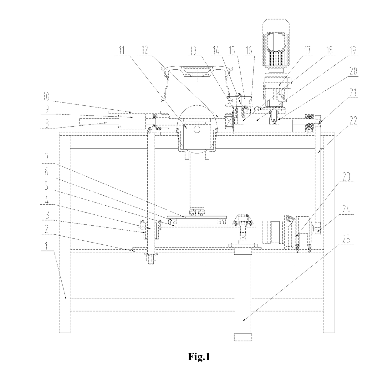
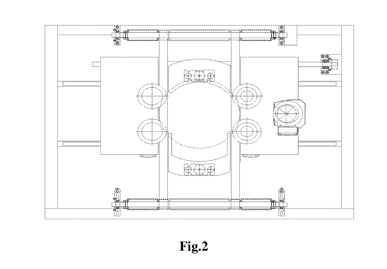
[0017]The wheel deburring device is composed of a machine frame 1, a bottom plate 2, guide sleeves 3, guide posts 4, a rising and falling plate 5, guide rails I 6, a sliding plate rack 7, a lead screw 8, a nut 9, a left sliding table 10, lifting cylinders 11, lifting plates 12, bearing blocks I 13, shafts I 14, V-type rollers 15, a right sliding table 16, a drive motor 17, belt pulleys I 18, a synchronizing belt I 19, a belt pulley II 20, a belt pulley III 21, a synchronizing belt II 22, a pneumatic motor 23, a belt pulley IV 24, rising and falling cylinders 25, a guide rail II 26, a sliding block 27, a servo electric cylinder I 28, a servo electric cylinder II 29, a link 30, a belt pulley V 31, a swinging plate 32, a synchronizing belt III 33, a brush 34, a belt pulley VI 35, a bearing block II 36, a servo motor 37, guide ra...


PUM


Abstract

The present invention relates to a wheel deburring device, which comprises a machine frame, motors, guide rails, a lead screw, sliding tables, cylinders, a brush, etc. Conveying roller ways enable a wheel to reach approximate middle positions of four V-type rollers, the wheel is lifted by lifting cylinders, a pneumatic motor drives the lead screw to rotate so as to enable a left sliding table and a right sliding table to drive the four V-type rollers to synchronously clamp the wheel, and a drive motor is used for achieving the rotation of the wheel in a clamped state. A servo motor drives the brush to rotate, rising and falling cylinders lift the brush through four guide posts, certain pressure is applied to the brush when the brush is in contact with flange corners of the wheel, then, the brush starts to remove burrs from the flange corners of the wheel, a servo electric cylinder I is used for achieving angle adjustment on the brush, and a servo electric cylinder II is used for achieving position adjustment on the brush through guide rails I; and when the brush is adjusted to an appropriate angle, the burr removal of rim corners can be completed, and thus the wheel deburring device can adapt to wheels of any model.

Description

[0001]This application claims priority from CN 201511006572.1, filed on Dec. 29, 2015, the entire content of which is incorporated herein by reference.TECHNICAL FIELD[0002]The present invention relates to a deburring device, and in particular to an online wheel deburring device.BACKGROUND ART[0003]In aluminum-alloy wheel production enterprises, deburring is an important link after a machining procedure and directly affects the painting effect of a follow-up painting procedure. At present, a deburring mode for wheel industry is that two large-disc brushes, i.e., an upper large-disc brush and a lower large-disc brush are used for brushing burrs of a back cavity and a front surface of a wheel, in this mode, when angles of the brushes are definite, the lower the linear velocity for brush hairs, the closer the brush central position, so that the problem that the burr processing effect on roots of ring flanges of wheels is poor is directly caused. Edge brush hairs of the traditional large...

Claims


Application Information

Patent Timeline
Patent Type & Authority Applications(United States)
IPC IPC(8): B24B9/04
CPCB24B9/04B24B5/44B24B5/46B24B19/28B24B29/005B24B41/02
Inventor XUE, BOWENGUO, JIANDONG
Owner CITIC DICASTAL
Why Eureka
Try Eureka