Substrate processing apparatus and substrate processing method

a substrate processing and substrate technology, applied in the direction of electrical equipment, semiconductor/solid-state device manufacturing, basic electric elements, etc., can solve the problems of large relative speed between the liquid film and the atmosphere, the liquid film of ipa will tear, and the liquid film will tear, etc., to shorten the period of time, the effect of rapid drying of the front surface of the substrate and even expansion of the opening

Active Publication Date: 2017-06-29
DAINIPPON SCREEN MTG CO LTD
View PDF12 Cites 22 Cited by
  • Summary
  • Abstract
  • Description
  • Claims
  • Application Information

AI Technical Summary

Benefits of technology

[0028]According to this method, when the opening is enlarged in a direction away from the rotational center position, an inert gas is supplied toward the rotational center position. Therefore, it is possible to evenly expand the opening from the rotational center position while quickly drying a low-surface-tension liquid at the peripheral edge of the opening. Additionally, the landing position is changed to at least two positions in accordance with the enlargement of the opening so that the landing position of the low-surface-tension liquid is placed outside the peripheral edge of the opening. Thereby, the low-surface-tension liquid is satisfactorily supplied to an area outside the peripheral edge of the opening. Therefore, the low-surface-tension liquid outside the peripheral edge of the opening is restrained from locally disappearing from on the front surface of the substrate because of evaporation or a centrifugal force. Therefore, the liquid film is excluded outwardly from the substrate while restraining or preventing the liquid film from being torn, and therefore a low-surface-tension liquid or processing liquid that has merged into the low-surface-tension liquid is restrained or prevented from remaining on the substrate in the form of liquid droplets. Thus, it is possible to swiftly dry the front surface of the substrate while restraining a low-surface-tension liquid and the like from remaining on the front surface of the substrate. This makes it possible to shorten a period of time during which surface tension caused by the low-surface-tension liquid or by processing liquid that has merged thereinto acts.
[0029]In one preferred embodiment of the present invention, the landing-position changing step includes a step of moving the landing position so that a distance between the peripheral edge of the opening and the landing position is kept constant. According to this method, in a process in which the opening is enlarged, the distance between the peripheral edge of the opening and the landing position is kept constant. Therefore, the liquid film of the low-surface-tension liquid that has become annular by the formation of the opening is more reliably restrained or prevented from being locally dried and being torn.
[0030]In one preferred embodiment of the present invention, the landing-position changing step includes a step of moving a nozzle that supplies a low-surface-tension liquid toward the front surface of the substrate in a direction along the front surface of the substrate. According to this method, it is possible to arbitrarily set and change the landing position by moving the nozzle. It is possible to change the landing position in a non-stepwise manner if the nozzle is moved in a non-stepwise manner. This makes it possible to cause the landing position to faithfully follow the enlargement of the opening of the liquid film.
[0031]In one preferred embodiment of the present invention, at least the replacing step, the liquid-film forming step, and the landing-position changing step include a step of heating the substrate. According to this method, the substrate is heated, and, as a result, it is possible to improve a speed at which the opening is enlarged while accelerating the evaporation of a low-surface-tension liquid at the peripheral edge of the opening. This makes it possible to dry the front surface of the substrate even more swiftly. Thereby, it is possible to further shorten a period of time during which surface tension caused by a low-surface-tension liquid or by processing liquid that has merged thereinto acts.

Problems solved by technology

Therefore, there is a fear that, after the supply of IPA is stopped, the liquid film of IPA will tear, and liquid droplets of IPA will remain on the substrate.
This causes a fear that the liquid film will tear.
Moreover, the linear speed of the liquid film in a rotational direction is large in the peripheral edge of the substrate, and therefore the relative speed between the liquid film and atmosphere is large, and evaporation progresses swiftly.
Therefore, the spraying force of the nitrogen gas locally acts on a part of the inner periphery of the annular liquid film of IPA, and hence becomes uneven with respect to the circumferential direction around the rotational center of the substrate.
This causes a fear that the liquid film of IPA will tear, and liquid droplets of IPA will remain on the substrate.
This causes a fear that a pattern collapse will occur.

Method used


Image

  • Substrate processing apparatus and substrate processing method
  • Substrate processing apparatus and substrate processing method
  • Substrate processing apparatus and substrate processing method

Examples


first preferred embodiment

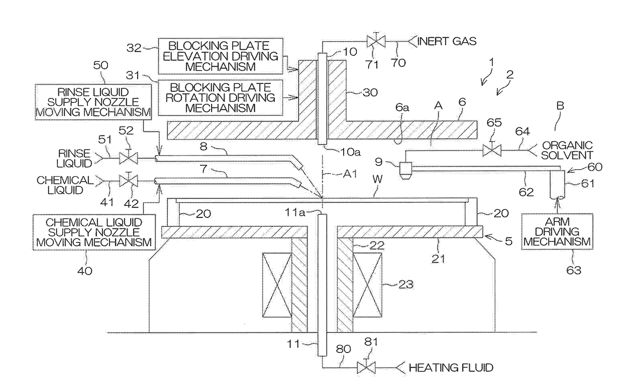
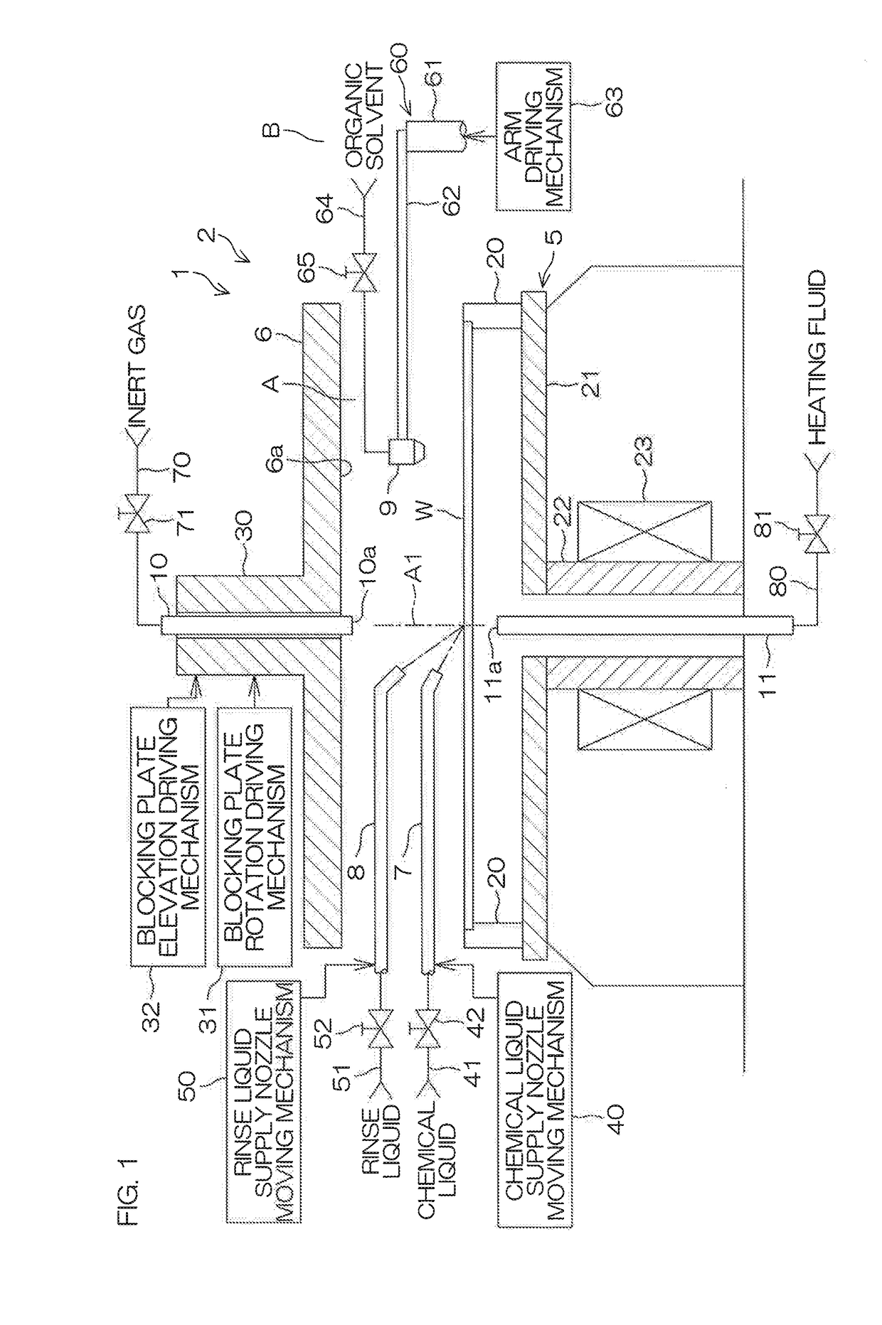
[0052]FIG. 1 is a schematic sectional view to describe an arrangement example of a processing unit included in a substrate processing apparatus 1 according to a first preferred embodiment of the present invention. The substrate processing apparatus 1 is a single substrate processing type apparatus that processes substrates W, such as silicon wafers, one by one. In this preferred embodiment, the substrate W is a circular substrate. A fine pattern (see FIG. 14) is formed on the front surface of the substrate W. The substrate processing apparatus 1 includes a processing unit 2 that processes a substrate W by use of a liquid. The substrate processing apparatus 1 may include a transfer robot that carries a substrate W into or out of the processing unit 2, in addition to the processing unit 2. The substrate processing apparatus 1 may include a plurality of processing units 2.

[0053]The processing unit 2 includes a spin chuck 5 that rotates a substrate W around a vertical rotational axis A1...

second preferred embodiment

[0100]FIG. 8 is a schematic sectional view to describe an arrangement example of a processing unit 2P included in a substrate processing apparatus 1P according to a second preferred embodiment of the present invention. In FIG. 8 and FIGS. 9 to 13 described later, the same reference sign is given to the same component as each component described above, and a description of the same component is omitted.

[0101]With reference to FIG. 8, points in which the processing unit 2P of the second preferred embodiment chiefly differs from the processing unit 2 of the first preferred embodiment shown in FIG. 1 are as follows. The processing unit 2P includes a fluid supply nozzle 11P instead of the fluid supply nozzle 11 of the first preferred embodiment (see FIG. 1). The fluid supply nozzle 11P is included in the substrate heating unit. The fluid supply nozzle 11P includes a center fluid supply nozzle 83 that supplies a heating fluid toward a central area including the rotational center position ...

third preferred embodiment

[0107]FIG. 9 is a schematic sectional view to describe an arrangement example of a processing unit 2Q included in a substrate processing apparatus 1Q according to a third preferred embodiment of the present invention.

[0108]Points in which the processing unit 2Q of the third preferred embodiment chiefly differs from the processing unit 2 of the first preferred embodiment shown in FIG. 1 are as follows. The processing unit 2Q includes a plurality of organic solvent supply nozzles 9Q instead of the organic solvent supply nozzle 9 (see FIG. 1). The organic solvent supply nozzle 9Q is included in the low-surface-tension liquid supply unit. The processing unit 2Q includes a heater 90 that heats the substrate W concentrically with the rotational center of the substrate W. The heater 90 is included in the substrate heating unit.

[0109]The plurality of organic solvent supply nozzles 9Q include a center position supply nozzle 100 that supplies an organic solvent toward the rotational center po...


PUM


Abstract

The controller is programmed to cause a low-surface-tension liquid supply unit to supply a liquid film of a low-surface-tension liquid to a front surface of a substrate so as to form a liquid film of the low-surface-tension liquid. The controller is programmed to control the substrate rotating unit and the inert gas supply unit so that an inert gas is supplied toward the rotational center position while rotating the substrate, thereby forming an opening spreading from the rotational center position to be formed in the liquid film, and enlarging the opening in a direction away from the rotational center position, and to control the landing-position changing unit to change the landing position of the low-surface-tension liquid to at least two positions except the rotational center position in accordance with enlargement of the opening so that the landing position is placed outside the peripheral edge of the opening.

Description

BACKGROUND OF THE INVENTION[0001]1. Field of the Invention[0002]The present invention relates to a substrate processing apparatus and a substrate processing method for processing a substrate by use of liquids. Examples of substrates to be processed include semiconductor wafers, substrates for liquid crystal displays, substrates for plasma displays, substrates for FEDs (Field Emission Displays), substrates for optical disks, substrates for magnetic disks, substrates for magneto-optical disks, substrates for photomasks, ceramic substrates, and substrates for solar cells.[0003]2. Description of the Related Art[0004]For example, a chemical liquid is supplied to a substrate substantially horizontally held by a spin chuck in a substrate processing operation that employs a single substrate processing type in which substrates are processed one by one. Thereafter, a rinse liquid is supplied to the substrate, and, as a result, the chemical liquid present on the substrate is replaced with the ...

Claims


Application Information

Patent Timeline
Patent Type & Authority Applications(United States)
IPC IPC(8): H01L21/02H01L21/324H01L21/67H01L21/306
CPCH01L21/02052H01L21/67034H01L21/324H01L21/30604H01L21/02041H01L21/02082H01L21/67017H01L21/02057H01L21/67028H01L21/67051H01L21/6708H01L21/67109H01L21/68792H01L21/02282H01L21/02307H01L21/02343H01L21/02623H01L21/67098H01L21/6715H01L21/6835H01L21/68764
Inventor TAKAHASHI, HIROAKIFUJIKAWA, KAZUNORIKOJIMARU, TOMONORIISHIDA, TOMOMASAHIGUCHI, AYUMIFUJIWARA, NAOZUMIKOMORI, KANAIWAHATA, SHOTA
Owner DAINIPPON SCREEN MTG CO LTD
Why Eureka
Try Eureka