
Method for preparing nanoparticles by using laser

Inactive Publication Date: 2017-07-06
SHONANO
View PDF2 Cites 2 Cited by
  • Summary
  • Abstract
  • Description
  • Claims
  • Application Information

AI Technical Summary

Benefits of technology

The present invention is a way to improve the production of nanoparticles using laser technology. It involves heating a mixture of a source material gas and a hexafluoride catalyst gas with a laser, which can save energy and increase the yield of nanoparticles. The invention aims to prevent the wastage of expensive source material gas and save energy by absorbing the laser's energy, reducing the energy needed to decompose the gas molecules.

Problems solved by technology

The liquid synthesis method is basically the batch process and has the difficulties in synthesizing the high purity nanoparticles since the method is necessarily accompanied with making contact with the foreign substances and other various solvents.
Said nanoparticle preparation methods by laser heating have advantage of producing high purity particles, but have problem of the low production yield which consequently generates the residual products of unreacted toxic source gases that may cause environmental damage if discarded.
Also, the reuse of residual products by recovery requires the complicated system and the high cost.

Method used


Image

  • Method for preparing nanoparticles by using laser
  • Method for preparing nanoparticles by using laser
  • Method for preparing nanoparticles by using laser

Examples


example 1

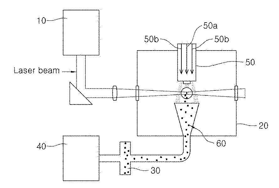
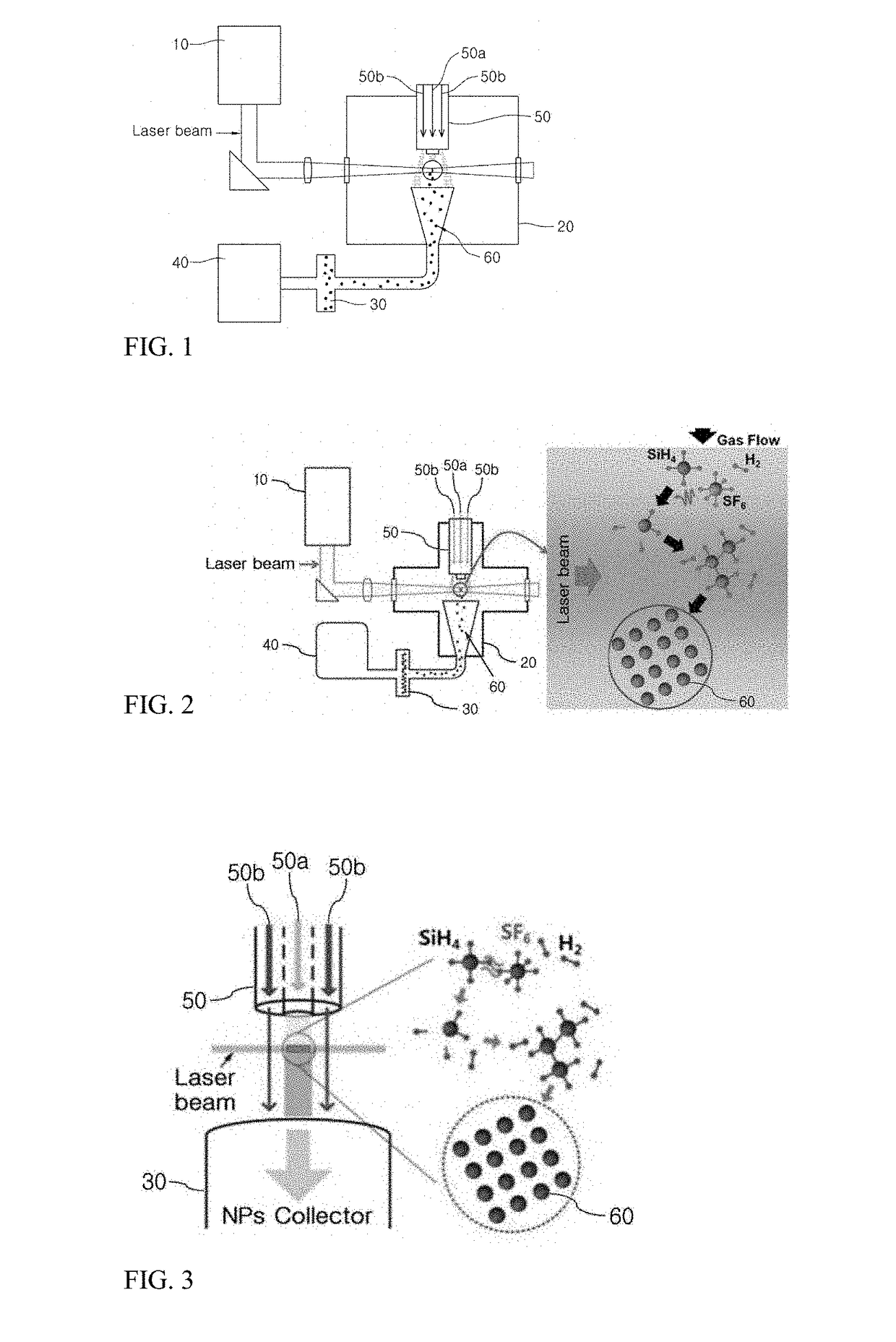
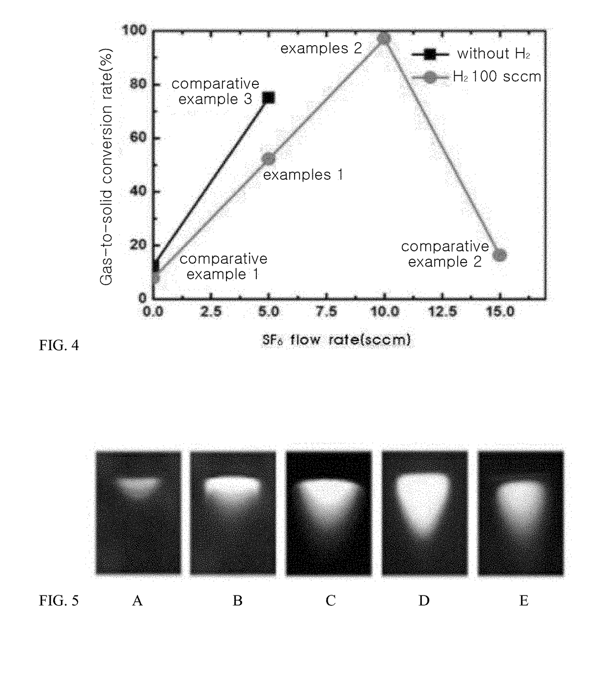
[0041]The mixture gas consisting of 25 sccm(100 volume part) of the source material gas (SiH4), 100 sccm(400 volume part) of the control gas (H2), and 5 sccm(20 volume part) of the catalyst gas (SF6), was supplied through the supply nozzle (50a) into the reaction chamber (20) having the internal pressure of 100 torr. Into the mixture gas was irradiated for 1 hour the continuous laser beam having wavelength of 10.6 μm through the laser emitter (10). As shown in FIGS. 2 and 3, the silicon nanoparticles (60) were produced and collected by the collector (30) by using the vacuum pump (40). In this example, the yield of Si-NPs having the particle size of 10-30 nm was 52.4%.

example 2

[0042]The mixture gas consisting of 25 sccm(100 volume part) of the source material gas (SiH4), 100 sccm(400 volume part) of the control gas (H2), and 10 sccm(40 volume part) of the catalyst gas (SF6), was supplied through the supply nozzle (50a) into the reaction chamber (20) having the internal pressure of 500 torr. Into the mixture gas was irradiated for 3 hour the continuous laser beam having wavelength of 10.6 μm through the laser emitter (10). As shown in FIGS. 2 and 3, the silicon nanoparticles (60) were produced and collected by the collector (30) by using the vacuum pump (40). In the example 2, the yield of Si-NPs having the particle size of 10-30 nm was 97.1%.

example 3

[0043]The mixture gas consisting of 25 sccm(100 volume part) of the source material gas (GeH4), 100 sccm(400 volume part) of the control gas (H2), and 5 sccm(20 volume part) of the catalyst gas (SF6) was used, and Ge-NPs were prepared by the method same as the example 1. The particle size of Ge-NPs was 20-100 nm and the yield was 53.7%.


PUM

PropertyMeasurementUnit
Internal pressureaaaaaaaaaa
Wavelengthaaaaaaaaaa
Volumeaaaaaaaaaa

Abstract

The present invention relates to a method for preparing nanoparticles by using laser and more particularly, a method for preparing nanoparticles by irradiating a laser beam to the mixture of a source material gas and a hexafluoride (SF6) catalyst gas, thereby improving the production yield of nanoparticles with energy saved. More particularly, the present invention provides the method for preparing the nanoparticles by using the laser wherein the laser beam of wavelength having the excellent energy absorption by the mixture gas of source material gas and catalyst gas is irradiated to the mixture gas so as to increase the reactivity of the source material gas with energy saved, which brings the effects of solving the problems of damaging environment due to the unreacted toxic source material gas incurred by the low production yield of the conventional nanoparticle preparation method and of making system complicated with the high cost when the discarded source gas is recovered and reused.

Description

TECHNICAL FIELD[0001]The present invention relates to a method for preparing nanoparticles by using laser and more particularly, a method for preparing nanoparticles by irradiating a laser beam to the mixture of a source material gas and a hexafluoride (SF6) catalyst gas, thereby improving the production yield of nanoparticles with energy saved.BACKGROUND OF THE INVENTION[0002]Nanotechnology, the core technology of the 21st century science, is recognized as the next generation growth engine that not only drives the technology innovation associated with the conventional manufacturing industry, but plays a key technology to better advance the future core businesses by converging the advanced technologies such as IT, BT and CT. The manufacturing methods of nanomaterials applied for such advanced technologies include laser heating method, liquid synthesis method, and solid synthesis method. The liquid synthesis method is basically the batch process and has the difficulties in synthesizi...

Claims


Application Information

Patent Timeline
IPC IPC(8): C01B33/021C01G17/00B01J27/12B01J19/08B82B3/00
CPCC01B33/021B01J19/08C01G17/00B01J27/12B82B3/0004B22F9/30C01B33/027C01P2004/64B01J2219/0883B22F1/054B01J19/121B01J2219/0892B01J37/349B01J21/08B01J37/0072B22F9/28B22F2999/00B01J35/393B01J35/30B01J35/23B22F3/105B22F3/1039
Inventor CHO, WON ILKIM, SEONG BEOM
Owner SHONANO
Learn More