Particle sorting device, particle sorting method, program, and particle sorting system
a particle sorting and particle technology, applied in the field of particle sorting devices, particle sorting methods, programs thereof, and particle sorting systems, can solve the problems of reducing the reliability of analysis data or reducing the accuracy and purity of sorting
- Summary
- Abstract
- Description
- Claims
- Application Information
AI Technical Summary
Benefits of technology
Problems solved by technology
Method used
Image
Examples
first embodiment
1. First Embodiment
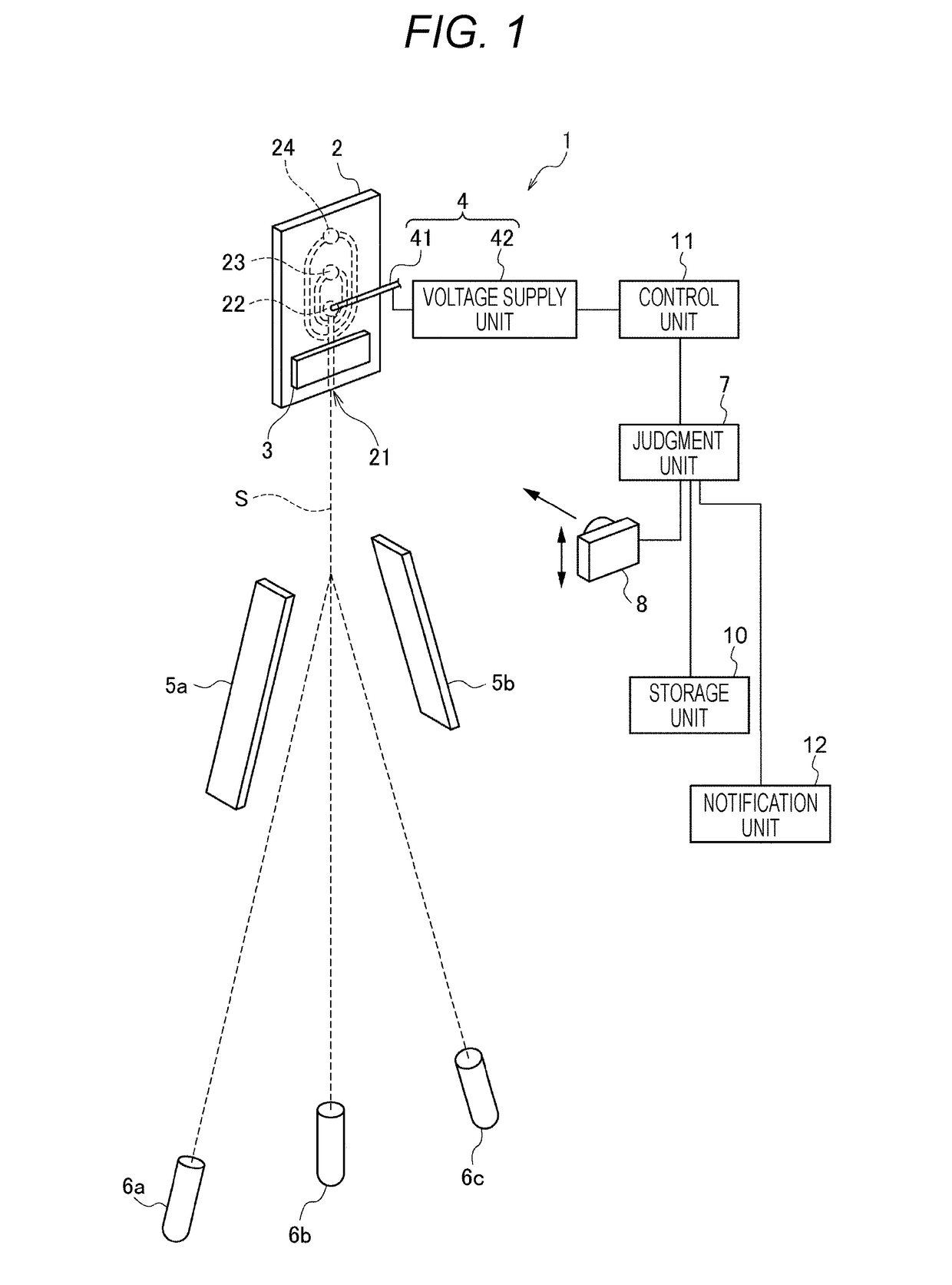
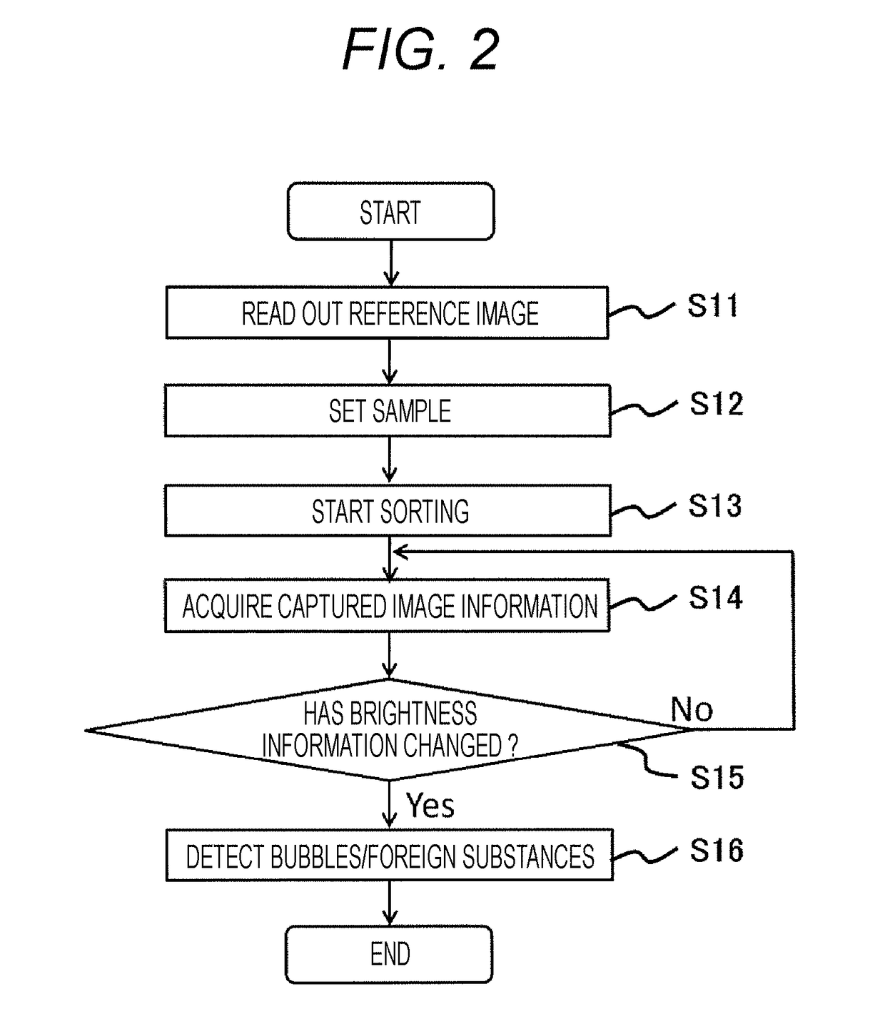
[0040]First, a particle sorting device 1 according to a first embodiment of the present disclosure will be described. FIG. 1 is a schematic view showing the structure of the particle sorting device 1 according to the first embodiment of the present disclosure.
[0041][Overall Structure of Device]
[0042]The particle sorting device 1 according to this embodiment is intended to detect bubbles, foreign substances, or the like in particle-containing droplets based on the information of a captured image, and as shown in FIG. 1, includes a microchip 2, a vibrating element 3, a charge unit 4, deflection plates 5a and 5b, a judgment unit 7, a storage unit 10, etc.
[0043][Particles]
[0044]Particles to be analyzed and sorted by the particle sorting device 1 according to this embodiment widely include cells, microorganisms, biologically-relevant microparticles such as ribosomes, and synthetic particles such as latex particles, gel particles, and industrial particles.
[0045]Examples...
second embodiment
2. Second Embodiment
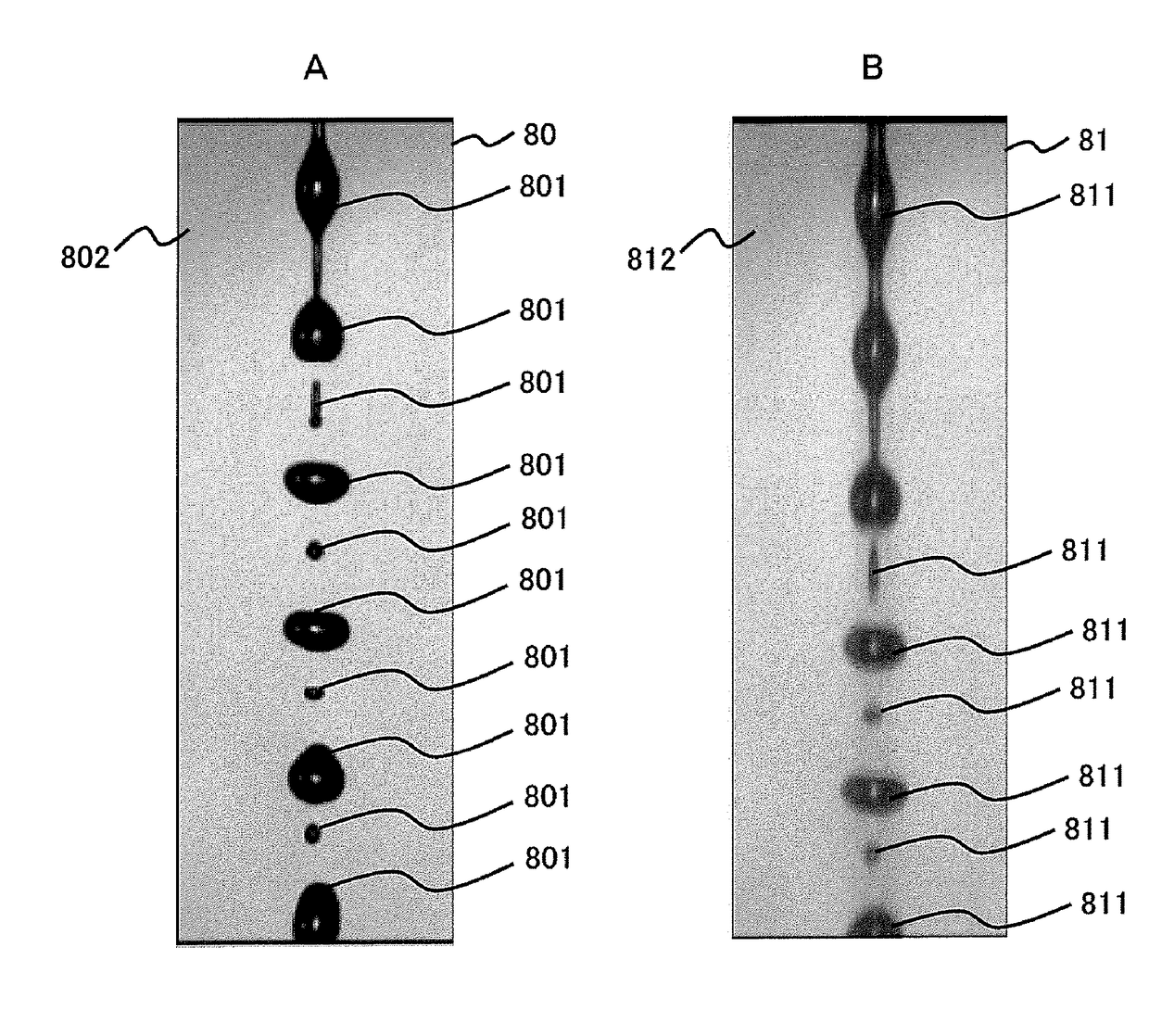
[0093]Hereinbelow, a particle sorting device 102 according to a second embodiment of the present disclosure will be described. FIG. 5 is a schematic view showing an example of the structure of the particle sorting device 102 according to the second embodiment of the present disclosure. FIG. 6 is a flow chart showing the summary of a method for detecting bubbles, foreign substances, or the like with the use of the particle sorting device 102 according to this embodiment. Bubbles, foreign substances, or the like often enter through the sample inlet 22, and therefore a stream containing no particle is often stable (i.e., droplets do not contain bubbles, foreign substances, or the like). The particle sorting device 102 according to this embodiment generates a stream containing no particle (non-particle-containing stream), and image information of droplets in this stream is used as the reference image information 80. Therefore, unlike the above-described first embodim...
third embodiment
3. Third Embodiment
[0097]Hereinbelow, a particle sorting device 103 according to a third embodiment of the present disclosure will be described. FIG. 7 is a schematic view showing an example of the structure of the particle sorting device 103 according to the third embodiment of the present disclosure. FIG. 8 is a flow chart showing the summary of a method for detecting bubbles, foreign substances, or the like with the use of the particle sorting device 103 according to this embodiment.
[0098]As shown in FIG. 7, unlike the particle sorting device 1 according to the first embodiment and the particle sorting device 102 according to the second embodiment, the particle sorting device 103 according to this embodiment includes a second imaging unit (camera) 9 that captures an image of droplets that have passed through between the deflection plates 5a and 5b. In the particle sorting device 103 according to this embodiment, the second imaging unit 9 captures an image of a side stream to obta...
PUM
 Abstract
Description
Claims
Application Information
 - R&D
- Intellectual Property
- Life Sciences
- Materials
- Tech Scout
- Unparalleled Data Quality
- Higher Quality Content
- 60% Fewer Hallucinations
Browse by: Latest US Patents, China's latest patents, Technical Efficacy Thesaurus, Application Domain, Technology Topic, Popular Technical Reports.
© 2025 PatSnap. All rights reserved.Legal|Privacy policy|Modern Slavery Act Transparency Statement|Sitemap|About US| Contact US: help@patsnap.com


