

Slot antenna
- Summary
- Abstract
- Description
- Claims
- Application Information
AI Technical Summary
Benefits of technology
Problems solved by technology
Method used
Image

Examples
embodiments
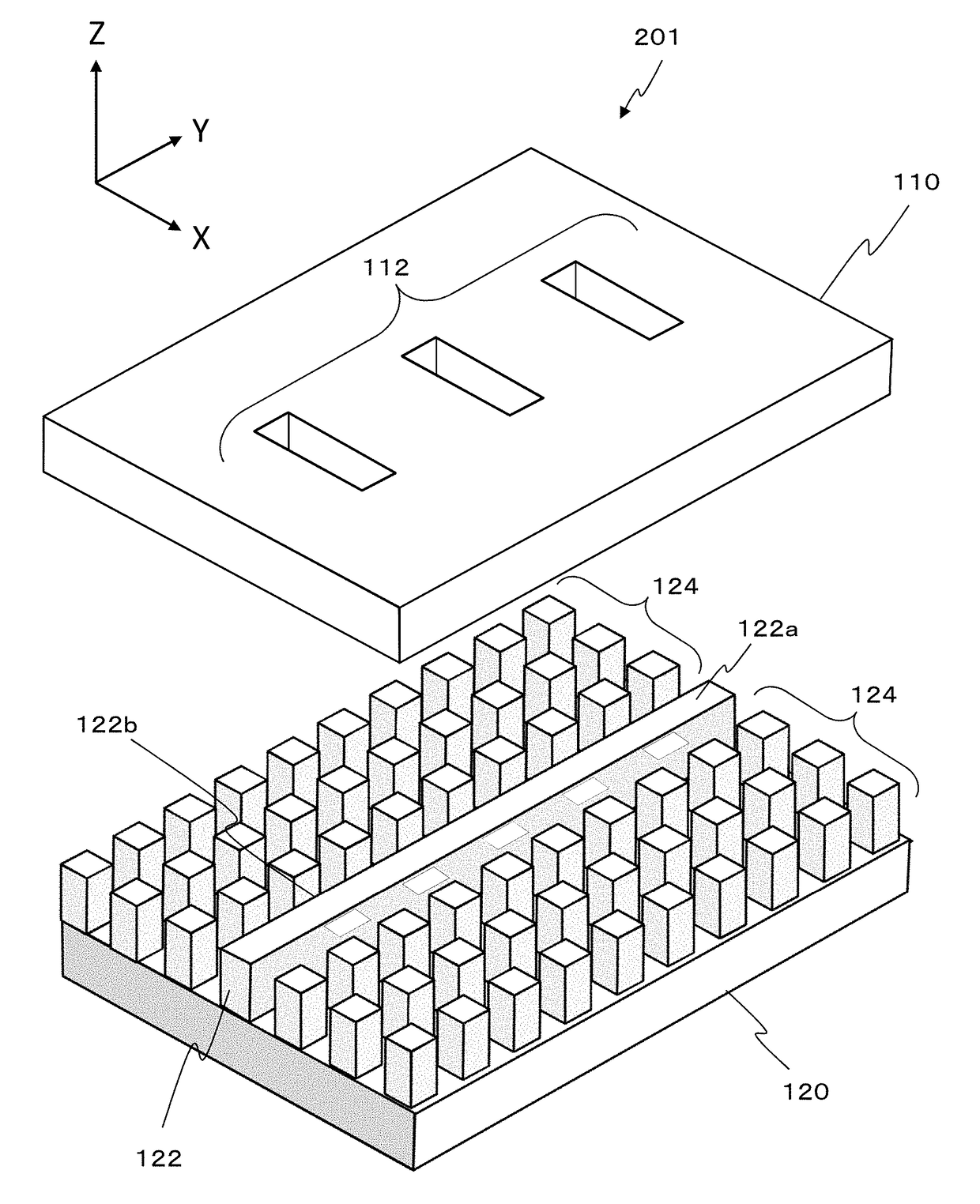
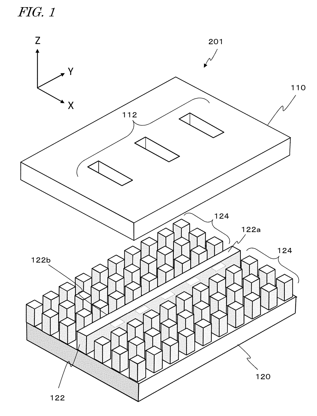
[0083]First, an exemplary fundamental construction for a slot antenna according to an embodiment of the present disclosure will be described.
[0084]In the slot antenna according to an embodiment of the present disclosure, electromagnetic waves can be guided by utilizing stretches of artificial magnetic conductor that are provided on both sides of a waveguide member; thus, electromagnetic waves can be radiated from or allowed to impinge on one or more slots that are made in the conductive member. The use of artificial magnetic conductor restrains radio frequency signals from leaking on both sides of the waveguide member (e.g., a ridge having an electrically-conductive waveguide face).
[0085]An artificial magnetic conductor is a structure which artificially realizes the properties of a perfect magnetic conductor (PMC), which does not exist in nature. One property of a perfect magnetic conductor is that “a magnetic field on its surface has zero tangential component”. This property is the...
application example 1
[0170]Next, as an Application Example of utilizing the above-described slot array antenna, an instance of an onboard radar system including a slot array antenna will be described. A transmission wave used in an onboard radar system may have a frequency of e.g. 76 gigahertz (GHz) band, which will have a wavelength λo of about 4 mm in free space.
[0171]In safety technology of automobiles, e.g., collision avoidance systems or automated driving, it is particularly essential to identify one or more vehicles (targets) that are traveling ahead of the driver's vehicle. As a method of identifying vehicles, techniques of estimating the directions of arriving waves by using a radar system have been under development.
[0172]FIG. 16 shows a driver's vehicle 500, and a preceding vehicle 502 that is traveling in the same lane as the driver's vehicle 500. The driver's vehicle 500 includes an onboard radar system which incorporates a slot array antenna according to any of the above-described embodimen...
application example 3
First Example of Communication System
[0431]The waveguide device and antenna device (array antenna) according to the present disclosure can be used for the transmitter and / or receiver with which a communication system (telecommunication system) is constructed. The waveguide device and antenna device according to the present disclosure are composed of layered conductive members, and therefore are able to keep the transmitter and / or receiver size smaller than in the case of using a hollow waveguide. Moreover, there is no need for dielectric, and thus the dielectric loss of electromagnetic waves can be kept smaller than in the case of using a microstrip line. Therefore, a communication system including a small and highly efficient transmitter and / or receiver can be constructed.
[0432]Such a communication system may be an analog type communication system which transmits or receives an analog signal that is directly modulated. However, a digital communication system may be adopted in order...
PUM
 Abstract
Description
Claims
Application Information