Valet parking method and system

a valet parking and parking method technology, applied in the direction of vehicle position/course/altitude control, process and machine control, instruments, etc., can solve the problems of inconvenient parking of vehicles, insufficient information for the central control system of the valet parking system, and inability to provide sufficient information, etc., to achieve adequate visibility of parking, reduce the effect of investment costs and increase the robustness of localization

Active Publication Date: 2017-07-13
ROBERT BOSCH GMBH
View PDF1 Cites 112 Cited by
  • Summary
  • Abstract
  • Description
  • Claims
  • Application Information

AI Technical Summary

Benefits of technology

[0021]Furthermore, the present invention also includes methods for the optimal positioning of parking-space sensors, like video-camera systems, for example, in the context of a given 3-D description of the parking environment or parking area, including all parking spaces, to minimize investment costs. With the aid of a size distribution of the parking vehicles to be anticipated on average, it is determined, based on geometrical considerations of the field of view of the planned sensor system and possible sight obstructions, at which positions of the given geometry of the...

Problems solved by technology

In those conventional valet parking systems, in which stationary sensors are employed to monitor the current state of occupancy of the parking area and/or the present positions of the autonomously parking or waiting vehicles, the problem exists that the field of view of these sensors may be restricted by inconveniently parked vehicles, especially very large or high vehicles, or by spatial structural conditions of the parking area such as columns, for example.
Therefore, there may no longer be sufficient information available to a central control system of the valet parking system in order to ideally utilize the p...

Method used


Image

  • Valet parking method and system
  • Valet parking method and system
  • Valet parking method and system

Examples


Embodiment Construction

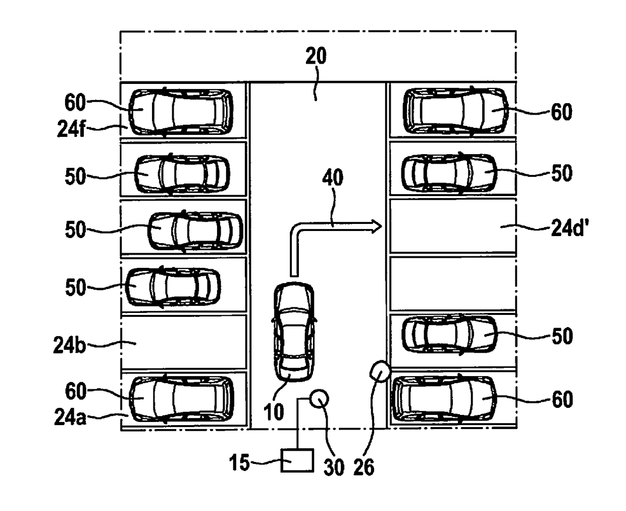
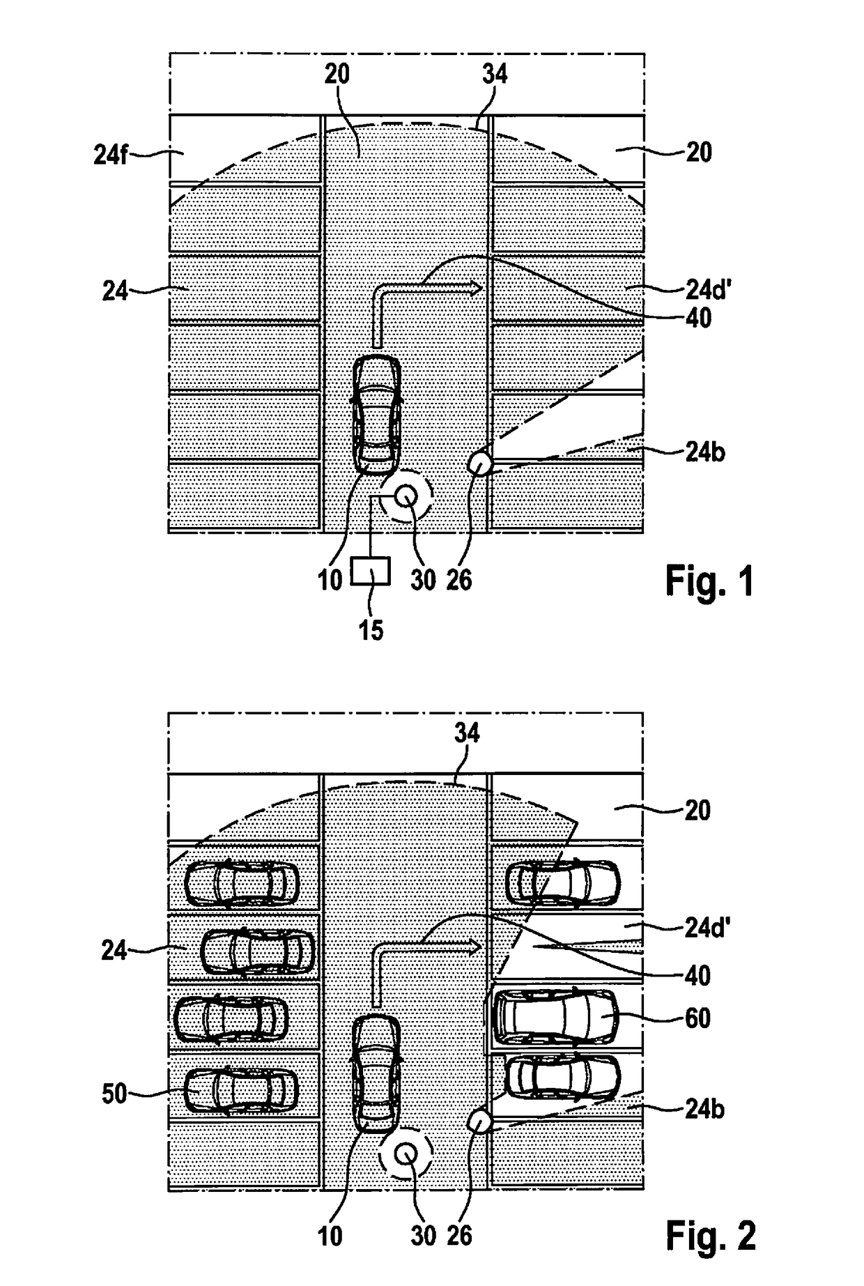
[0028]FIG. 1 shows a bird's-eye view of a parking area 20 with multiple parking spaces 24. For example, parking area 20 may be one level of a parking garage or an outdoor parking place. A vehicle 10 is about to move autonomously along a trajectory 40 to an assigned parking space 24′. To that end, vehicle 10 must be designed to move autonomously, thus, without the presence or assistance of a driver, to a specific destination 24′. For instance, vehicle 10 moves automatically along an intended trajectory 40, or a suitable control unit of the vehicle itself calculates a trajectory 40 as a function of determined or received surround-field information and causes vehicle 10 to travel over it. Autonomous vehicles 10 of this kind are known in various designs from the related art, and therefore shall not be further discussed here.

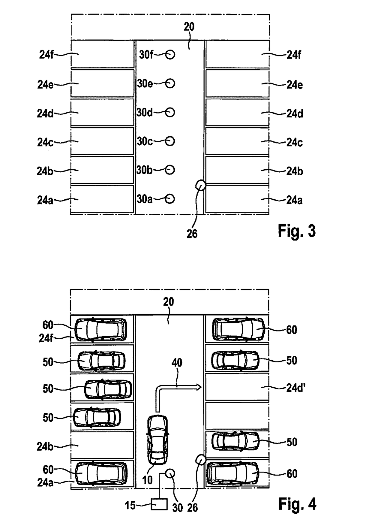
[0029]In the front region, parking area 20 has a single parking-space sensor 30 in the form of a video camera with a field of view 34, which is part of a parking-spa...


PUM


Abstract

A valet parking system for automatically bringing a vehicle to a parking space within a predefined parking area. The valet parking system includes a central control unit and a parking-space monitoring system having a stationary parking-space sensor. The parking-space monitoring system is designed to detect the current state of occupancy of the parking spaces of the parking area and to transmit that to the central control unit. The parking-space monitoring system may localize all autonomously moving or waiting vehicles that are currently in transit autonomously within the parking area either to be brought to their assigned parking space or received by their driver at a predefined pick-up location, and to transmit information about the present position of all these vehicles to the central control unit. A free parking space is assigned to the vehicle by the central control unit as a function of the geometrical dimensions of the vehicle.

Description

FIELD[0001]The present invention relates to a valet parking method and a valet parking system for automatically bringing a vehicle to an assigned parking space within a predefined parking area.BACKGROUND INFORMATION[0002]A valet parking method is to be understood here specifically as a method in which a driver of a vehicle is able to drop it off at a predetermined drop-off location, whereupon the vehicle is parked in automated fashion or by service personnel and is provided to the driver again upon request or appointment. The present invention deals especially with a valet parking method, in which vehicles are parked by an automatic system. In this context, the vehicles move without the assistance of a human driver to an assigned parking space and back again to a pick-up location.[0003]The German Patent No. DE 10 2012 222 562 describes a system for managed parking lots, what is referred to as a valet parking system, for transferring a vehicle from a start position to a destination p...

Claims


Application Information

Patent Timeline
IPC IPC(8): G08G1/14B60W30/06G05D1/02G08G1/04
CPCG08G1/146G08G1/142G08G1/04B60W30/06G05D1/0088G05D1/0212B60W2420/42B60W2550/40G05D1/0285G05D1/0246G05D1/0282G05D2201/0213B60W2556/50B60W2554/00B60W2556/65B60W2556/55B60W2556/45B60W2554/20B60W2420/403
Inventor MIELENZ, HOLGER
Owner ROBERT BOSCH GMBH
Why Eureka
Try Eureka